11
ENG
Hecu
CO
2
+0300085EN rel. 2.2 - 07.05.2019
2.4 12 A single-phase inverter PSD2
For further details on the electrical and mechanical specifi cations, see
technical leafl et +0500120IE
3
4
5
6
7
ST
O
A
B
cut
this
area
and
access
to
DIP
switches
to
set
the
ID
(network)
address
E
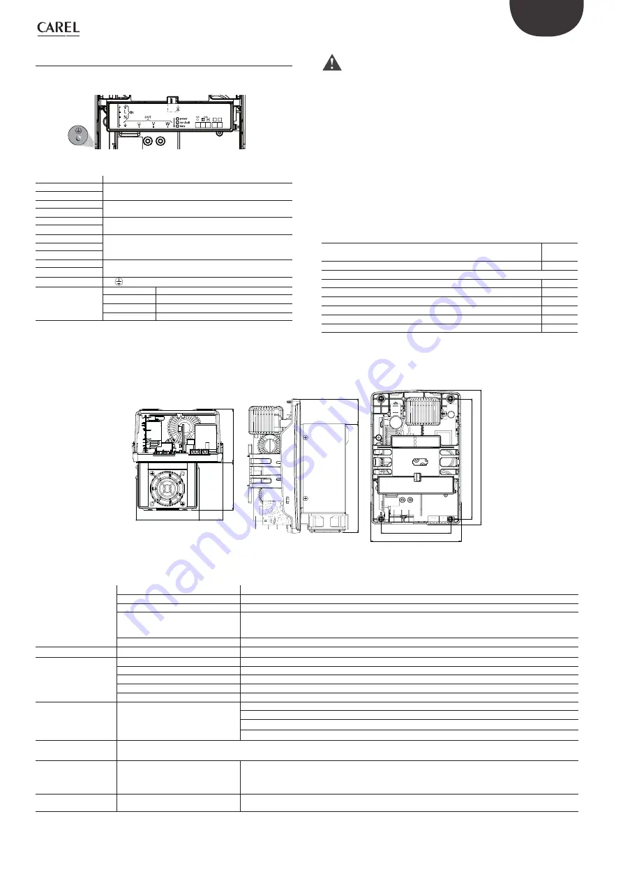
Fig. 2.f
Description of the terminals:
Ref.
Description
L, N
Single-phase power input
Spade connectors
PE
(*)
U, V, W
Motor output
Spade connectors
PE
(*)
-DC
DC bus output
Spade connectors
+DC
GND (0V)
RS485/ModBus® connection
3-pin plug-in terminals
Tx/Rx+
Tx/Rx-
STO1
STO safety input
2-pin plug-in terminals
STO2
E
PE
Earth screw
F (LED)
POWER (green) drive powered
RUN (green)
drive running
FAULT (red)
drive alarm
DATA (yellow)
communication active
Tab. 2.h
(*)
The earth connections inside the drive are wired together and to the PE.
Important:
•
before carrying out any maintenance, disconnect the drive and the
control circuits from the power supply by moving the main system
switch to “off ”. Once having powered down the drive, wait at least 5
minutes before disconnecting the electrical cables;
•
always make sure that the motor has come to a complete stop. Freely
rotating motors may generate dangerous voltages across the Power+
terminals, even when this is not powered;
Rated values
The following table shows the rated input current and output current
values, as well as the specifi cations for sizing the cables (cross-section,
maximum length) and the fuses. The values refer to an operating
temperature of 60°C and a switching frequency of 8 kHz, unless otherwise
specifi ed.
PSD10102BA
Rated input current at 230 V
19.2 to
16 A
Fuse or type B circuit breaker
25 A
Power cable size
4 mm
2
Rated output current
12 A
Rated output power at 230 V
3.8 kW
Maximum total dissipation
270 W
Maximum dissipation on the heat sink
150 W
Min. motor cable size
2.5 mm
2
Max. motor cable length
5 m
Tab. 2.i
Dimensions
87.1
103
39.3
78
113.4
197
220
148
40.9
177.7
Fig. 2.g
Main technical specifi cations
Environmental condi-
tions
Storage temperature
-40T60°C
Operating temperature
-20T60°C
Humidity
< 95% RH non-condensing
Altitude
Maximum allowed: 2000 m above sea level
Up to 1000 m asl without derating
Derating in terms of maximum output current: 1% /100m
Environmental pollution level
3
Power supply
Input voltage
200 - 240V / 105 -125V ± 10%, 50/60Hz, 1~
~
Motor output
Output voltage
0 - Input voltage
Output frequency
0 - 500 Hz
Frequency resolution
0.1 Hz
Maximum cable length
see paragraph 5.1
Switching frequency
4, 6, 8 kHz
Functions
Protection functions
Drive: short circuit, overcurrent, earth fault, overvoltage and undervoltage, overtemperature
Motor: overload (150% Inom for 1 minute), stall
System: loss of communication,
Safety: STO (Safe Torque Off ), locked rotor
Control unit
Each drive must be connected in the network via Modbus® to a CAREL pCO or other manufacturer’s controller that manages the drives with Master/
Slave logic.
Inputs
STO (Safe Torque Off )
Voltage-free contact input, reinforced insulation (12 V SELV circuit):
open contact voltage: <24 V
closed contact current: 40 mA typical
max. cable length 25 m
Outputs
DCbus power supply
for auxiliary devices
395 Vdc ± 10 Vdc, 1.9 A max for PS2**122***** models;
max. cable length 1 m - shielded cable, minimum cross-section 1 mm
2
Содержание Hecu CO2
Страница 2: ......
Страница 4: ...4 ENG Hecu CO2 0300085EN rel 2 2 07 05 2019...
Страница 6: ......
Страница 61: ...61 ENG Hecu CO2 0300085EN rel 2 2 07 05 2019 9 2 Software revision history New version 3 0 012...
Страница 62: ...62 ENG Hecu CO2 0300085EN rel 2 2 07 05 2019 Notes...
Страница 63: ......


