35
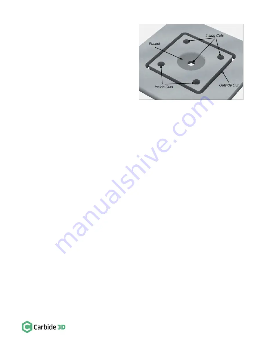
Now, let’s take a look at the first three toolpaths again,
this time with a little visual context:
•
Inside Cut: Offsets the cutter to the inside of the
feature
•
Outside Cut: Offsets the cutter to the outside of
the feature
•
Pocket: Clears everything inside the feature
Assuming we are using a
1
/
8
″
cutter, look at the image at
right and try to imagine what would happen if you cut on
the wrong side of the feature (think of the individual
shapes in the part as features).
For instance, had you chosen an inside cut for the profile
(the outermost toolpath that frees your part from the stock) instead of an outside cut, your part would end up ¼
″
smaller than you had intended.
Why? Because your cutter has a kerf of
1
/
8
″
. So, if you cut
inside
the line (on both sides of the part), then you would
have overcut ¼
″
of unintended material.
The center feature (a pocket toolpath) will clear out everything
inside
of the selected feature. The toolpath in our
example is slightly misleading because there is also a hole in the middle of the pocket. To accomplish this result,
you would need to apply a pocket operation to the larger circle, and then an inside cut on the smaller circle inside
it. Defining the parameters accordingly will allow each feature to reach a different depth of cut.
Max Depth
Max depth is your target depth. Defining this parameter tells a toolpath how deep it should cut into the material
when the operation is finished. This is not the same as depth per pass. In fact, think of depth of cut as the final
depth for all of the depth passes. It is important to remember also that the software will calculate how many passes
it will take to reach the depth of cut. You do not have to define that. If you tell the software how deep to cut a
feature, the rest will be automatically calculated.
Feeds and Speeds
“Feeds and speeds” refers to how fast the cutter should spin and how fast the cutter should be moved through the
material
—
depending on the nature of the material and the choice of end mill. Collectively, speeds and feeds is
referring to these parameters, and their values for a given use-case. The good news is
you don’t have to worry
about speeds and feeds
—
unless you want to. MeshCAM automatically calculate speeds and feeds based multiple
project variables, including machine, material, and cutter and Carbide Create uses a curated set of speeds and
feeds based on material and use-case.
If you’d like to learn more about speeds and feeds in order to try to achieve a faster run
-time or a cleaner finish,
and watch the
Making Sense of Speeds and Feeds video
TL;DR Summary
When creating toolpaths, you need to choose which tool will work best for a feature, the toolpath type, and the
depth of cut. From this information, and the type of material you’re using, the software will automatically calculate
the appropriate speeds and feeds for your toolpath (though advanced users can input their own speeds and feeds).


