background image

Chapter 1

1-23

5) Open the manual feed tray.

6) Place an A4 or LTR sheet of plain paper in the manual feed tray.

F-1-17

7) Press the OK key. The machine will start cleaning the fixing pressure roller.

4.Cleaning the Transfer roller

If the reverse side of the printed paper is stained, the transfer roller can be dirty. If the reverse side of the printed paper is stained, clean the transfer roller in the user

mode.

1) Press the additonal functions key to enter the user mode.

2) Using the left and right arrow keys, display the "ADJUST./CLEANING".

3) Press the OK key.

4) Using the left and right arrow keys, select "TRANS. ROLR CLEAN". Next, press the OK key. Cleaning will start.

5. Cleaning the ADF roller

If black streaks are seen on the printed paper from the ADF, the internal roller in the ADF can be dirty. If this symptom occurs, clean the internal roller in the user

mode.

1) Press the additonal functions key to enter the user mode.

2) Using the left and right arrow keys, display the "ADJUST./CLEANING" menu.

3) Press the OK key.

4) Using the left and right arrow keys, select "FEEDER CLEANING". 

5) Load five sheets of paper in the ADF and press the OK key. Cleaning will start.

Содержание Laser Class 810

Страница 1: ...SERVICE MANUAL LASER CLASS 810 830i COPYRIGHT 2010 CANON INC CANON Laser Class 810 830i Rev 1 PRINTED IN U S A March 26 2010 Rev 1 Main Body SM cover qxp 11 2 2007 12 07 PM Page 1...

Страница 2: ......

Страница 3: ...need arises In the event of major changes in the contents of this manual over a long or short period Canon will issue a new edition of this manual The following paragraph does not apply to any countri...

Страница 4: ...uiring care to avoid combustion fire Indicates an item prohibiting disassembly to avoid electric shocks or problems Indicates an item requiring disconnection of the power plug from the electric outlet...

Страница 5: ...ed to indicate Low The voltage value how ever differs from circuit to circuit In addition the asterisk as in DRMD indicates that the DRMD signal goes on when 0 In practically all cases the internal me...

Страница 6: ......

Страница 7: ...EPORT SETTINGS 1 18 1 2 3 11 SYSTEM SETTINGS 1 19 1 2 4 Maintenance by the User 1 22 1 2 4 1 User Maintenance Items 1 22 1 2 4 2 Cleaning 1 22 1 2 5 Safety 1 24 1 2 5 1 Safety of Toner 1 24 1 2 5 2 Sa...

Страница 8: ...3 3 3 1 5 Reader Controller PCB 3 4 3 1 6 Power Supply PCB 3 4 3 1 7 NCU PCB 3 4 3 1 8 Modular Jack PCB 3 4 3 1 9 Modem PCB 3 4 3 2 Basic Sequence 3 6 3 2 1 Basic Sequence 3 6 Chapter 4 Original Expos...

Страница 9: ...ler 5 10 5 4 3 Feed Roller 5 10 5 4 3 1 Removing the Feed Roller 5 10 5 4 4 Pick up Motor 5 10 5 4 4 1 Removing the ADF Pickup Motor 5 10 5 4 5 Read Motor 5 11 5 4 5 1 Removing the Read Motor 5 11 5 4...

Страница 10: ...of Paper 8 4 8 4 Duplex Unit 8 5 8 4 1 Outline 8 5 8 5 Manual Feed Pickup Unit 8 6 8 5 1 Outline 8 6 8 5 2 Retry Pickup 8 6 8 5 3 Detecting the Size of Paper 8 6 8 6 Parts Replacement Procedure 8 7 8...

Страница 11: ...he Fixing Unit 9 6 9 4 1 2 Installing the fixing unit 9 8 9 4 2 Fixing Film Unit 9 8 9 4 2 1 Removing the Fixing Film Unit 9 8 9 4 3 Fixing Pressure Roller 9 9 9 4 3 1 Removing the Pressure Roller 9 9...

Страница 12: ...12 Modem PCB 10 14 10 4 12 1 Removing the Modem PCB 10 14 10 4 13 Modular Jack PCB 10 15 10 4 13 1 Removing the Modular Jack PCB 10 15 10 4 14 Network PCB 10 15 10 4 14 1 Removing the Network PCB if...

Страница 13: ...Data 13 2 13 4 ADF 13 4 13 4 1 Outline 13 4 13 4 1 1 Outline 13 4 13 4 1 2 Preparing a Test Sheet for Adjustment 13 4 13 4 2 Adjusting the Electrical System 13 4 13 4 2 1 Adjusting the Magnification...

Страница 14: ...iled Discussions of Bit 2 16 11 16 3 4 3 Detailed Discussions of Bit 3 16 11 16 3 4 4 Detailed Discussions of Bit 4 16 11 16 3 4 5 Detailed Discussions of Bit 5 16 11 16 3 4 6 Detailed Discussions of...

Страница 15: ...el for fax tel switchover 16 19 16 5 13 024 pseudo RBT transmission level at time of fax tel switchover 16 19 16 5 14 025 Answering machine connection function signal detection time 16 19 16 5 15 027...

Страница 16: ...4 Margin adjustment at the trailing edge of the copy 16 28 16 7 2 15 055 Margin adjustment at the right edge of the copy 16 28 16 7 2 16 056 Margin adjustment at the left edge of the copy 16 28 16 8 N...

Страница 17: ...1 1 Overview of Upgrade 17 1 17 1 2 Overview of UST 17 1 17 2 Making Preparations 17 2 17 2 1 Connection 17 2 17 2 2 Preparations for the System Software 17 2 17 3 Downloading System Software 17 2 17...

Страница 18: ...Contents...

Страница 19: ...Chapter 1 Introduction...

Страница 20: ......

Страница 21: ...7 1 2 3 8 TIMER SETTINGS 1 18 1 2 3 9 ADJUST CLEANING 1 18 1 2 3 10 REPORT SETTINGS 1 18 1 2 3 11 SYSTEM SETTINGS 1 19 1 2 4 Maintenance by the User 1 22 1 2 4 1 User Maintenance Items 1 22 1 2 4 2 Cl...

Страница 22: ......

Страница 23: ...n 0017 7471 Pickup Other Accessories F 1 1 1 Host machine 2 FXL Cassette Feeder 8 option 3 Handset Kit 10 for US HANDSET REST FP TEL 6 KIT LONG CORD except for US HK and SPL HANDSET REST FP TEL 3 KIT...

Страница 24: ...Function IMAGE CLASS 830i FAX L3000IP i SENSYS FAX L3000IP Copy Std Std Std FAX Std Std Std ADF Std Std Std Print Std Std Std PC Fax RemoteUI Network SEND Std Option Color Send kit M1 Option Color Sen...

Страница 25: ...Pickup Other Accessories F 1 3 1 Host machine 2 FXL Cassette Feeder 8 option 3 Handset Kit 10 for US HANDSET REST FP TEL 6 KIT LONG CORD except for US HK and SPL HANDSET REST FP TEL 3 KIT LONG CORD fo...

Страница 26: ...unction table 1 UFR II LT Printer kit X1 option Function IMAGE CLASS 810 FAX L3000 i SENSYS FAX L3000 Copy Std FAX Std ADF Std Print Option UFRII LT Printer kit X1 PC Fax RemoteUI Network SEND None So...

Страница 27: ...DF 8 Paper cassette 2 Slide guides 9 Stack support 3 Document feeder tray 10 Left cover 4 Document delivery tray 11 ADF scanning area 5 Delivery tray 12 Multi purpose tray 6 Paper stopper 13 Slide gui...

Страница 28: ...Chapter 1 1 6 1 2 1 2 External View Rear 0017 8460 F 1 6 1 USB port 5 Handset jack 2 Ethernet port 6 Power socket 3 Telephone line jack 7 Main power switch 4 External device jack 1 2 3 4 5 6 7...

Страница 29: ...linder 4 ADF delivery roller 15 Transfer charging roller 5 Laser scanner unit 16 Photopositive drum 6 Cassette 17 Primary charging roller 7 Pickup roller 18 Fixing film unit 8 Feed roller 19 Fixing pr...

Страница 30: ...On the Power Switch 0016 7895 The machine possesses the main power switch Normally i e unless the machine is in a sleep state the machine will be supplied with power when you turn on its main power s...

Страница 31: ...ring printing or fax data transmission reception Be sure to operate the main power switch while the Processing Data lamp on the control panel is not lit Turning off the main switch during printing or...

Страница 32: ...Chapter 1 1 10 During downloading Do not turn off the power switch or ON OFF switch on the control panel Turning off the main power switch during downloading can make this machine inoperative F 1 10...

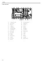
Страница 33: ...uality key 8 Serial No key 22 key 9 Log In Out key 23 OK key 10 Copy Fax key 24 key 11 Clear key 25 Back key 12 Energy Saver key 26 LCD display 13 Stop key 27 System Monitor key 14 Error indicator 1 O...

Страница 34: ...nsity indicator 20 Reset key 6 Image Quality indicator 21 Fax Send key 7 View Settings key 22 Color indicator 8 Serial No key 23 Image Quality key 9 Log In Out key 24 key 10 Copy key 25 OK key 11 Clea...

Страница 35: ...ys 6 Direct TX key 2 One Touch Key Panels 7 Hook key 3 Address Book key 8 Pause key 4 Stamp key 9 Recall key 5 Delayed TX key 10 Coded Dial key 1 2 3 4 5 6 8 9 10 7 M1 01 M2 02 M3 03 M4 04 05 06 07 08...

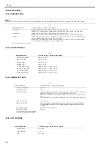
Страница 36: ...nit is attached Additional Functions Available Settings indicates factory settings MONITOR VOLUME ON 1 3 OFF RING VOLUME ON 1 3 OFF ENTRY TONE ON 1 3 OFF ERROR TONE ON 1 3 OFF TX JOB DONE TONE ERROR O...

Страница 37: ...NORMAL LOW HIGH TX TERMINAL ID PRINTING POSITION OUTSIDE IMAGE INSIDE IMAGE TELEPHONE MARK FAX TEL COLOR TX GAMMA 1 GAMMA 1 8 GAMMA 2 2 GAMMA 1 0 GAMMA 1 4 SHARPNESS 1 1 4 7 COLOR TX SCAN SET 1 SPEED...

Страница 38: ...150dpi 200x100dpi ORIGINAL TYPE TEXT PHOTO TEXT PHOTO FTP HOST NAME max 120 digits NAME max 16 characters including spaces FILE PATH max 120 digits LOGIN NAME max 24 characters PASSWORD max 24 charact...

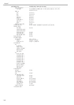
Страница 39: ...max 16 characters including spaces FILE PATH max 120 digits LOGIN NAME max 24 characters PASSWORD max 24 characters SMB 1 HOST NAME max 120 digits NAME max 16 characters including spaces FILE PATH max...

Страница 40: ...ONE SETTING GMT 12 00 GMT 9 00 GMT 12 00 DATE TYPE SELECT YYYY MM DD MM DD YYYY DD MM YYYY AUTO SLEEP TIME ON 3 5 30MIN OFF AUTO CLEAR TIME ON 1 2 9MIN OFF DAYLIGHT SV TIME OFF ON BEGIN DATE TIME MONT...

Страница 41: ...00000 999999 ERASE YES NO PAGE TOTALS VIEW PAGE TOTALS TOTAL PRINT COPY SCAN COLOR SCAN PRINT CLEAR ALL TOTAL YES NO PRINT LIST YES NO PDL JOBS W OUT ID ON OFF MANAGE USER ID ON OFF NETWORK SETTINGS 1...

Страница 42: ...ETHERNET DRIVER AUTO DETECT AUTO MANUAL DUPLEX Half duplex Full duplex ETHERNET TYPE 10 BASE T 100 BASE TX NETWORK INFO IPv4 IP ADDRESS SUBNET MASK GATEWAY ADDRESS DOMAIN NAME HOST NAME IPv6 LINK LOCA...

Страница 43: ...D IMAGE FORMAT TIFF B W PDF DIVIDE INTO PAGES ON OFF i FAX 2 ON OFF FORWARD IMAGE FORMAT TIFF B W PDF DIVIDE INTO PAGES ON OFF FORWARD ERR SET PRINT ON OFF STORE TO MEMORY ON OFF REMOTE UI ON OFF REST...

Страница 44: ...black streaks are seen on the printed paper the fixing pressure roller can be dirty If black streaks are seen on the printed paper clean the fixing pressure roller in the user mode Be sure to clean th...

Страница 45: ...ng the left and right arrow keys display the ADJUST CLEANING 3 Press the OK key 4 Using the left and right arrow keys select TRANS ROLR CLEAN Next press the OK key Cleaning will start 5 Cleaning the A...

Страница 46: ...er unit is fully enclosed in a protective housing and external covers so that its light will not escape outside as long as the machine is used normally 1 2 5 3 CDRH Regulations 0016 7900 The Center fo...

Страница 47: ...autions as to the replacement and disposal of lithium battery 0016 7903 The machine s image processor is equipped with a fixed lithium battery Risk of explosion if Battery is replaced by an incorrect...

Страница 48: ...gh temperature humidity or low temperature humidity areas subject to rapid changes in temperature or humidity or areas subject to condensation e g near an air conditioner d Avoid areas exposed to corr...

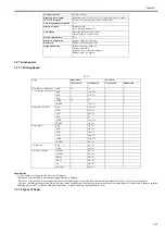
Страница 49: ...19 0 sec or less A4 LTR First copy time 13 0 sec or less A4 LTR First print time 9 0 sec or less A4 LTR Print speed A4 22cpm LTR 23cpm Printing resolution 1200 dpi enhanced x 600 dpi Cassette paper s...

Страница 50: ...0 mm W X 481 mm D X 580 mm H with optional cassette unit Weight Approx 25 5kg including toner cartridge 0 9kg Option FXL Cassette Feeder 8 Color Send Kit M1 except for Laser Class 830i Handset Stamp U...

Страница 51: ...00 sheets plain paper 80g m2 80 sheets heavy paper 91 to 105g m2 50 sheets heavy paper 106 to 128g m2 40 sheets label 10 sheets envelope OHP 50 sheets post card Host interface USB standard 10BASE T 10...

Страница 52: ...eets or less 1 small size A4R B5R A5R B6 LTRR SMTR 2 large size LGL Mixed original sizes no Original AE detection no Original size recognition no Stamp yes option Applicable lines Subscriber telephone...

Страница 53: ...CI transmission Answering machine connection Yes Remote reception ID input method ID 2 characters default 25 Auto dialing One touch dialing FAX80 TEL80 Speed dialing FAX120 TEL120 Delayed transmissio...

Страница 54: ...R LGL Weight 64 to 90 g m2 56 to 128 g m2 64 to 90 g m2 Quantity Max 500 sheets Max 100 sheets by pickup inlet Paper type Plain paper 80 g m2 Yes Yes Yes Recycled paper Yes Yes Yes Colored paper Yes Y...

Страница 55: ...Chapter 1 1 33...

Страница 56: ......

Страница 57: ...Chapter 2 Installation...

Страница 58: ......

Страница 59: ...2 6 2 2 4 Changing the Cassette Paper Size 2 7 2 2 5 Connecting the Cable 2 8 2 2 6 Connecting the Cable 2 8 2 2 7 Checking the Image Quality 2 9 2 2 8 Setting the Date and Time 2 9 2 2 9 Checking the...

Страница 60: ......

Страница 61: ...ply C Zone C Problems associated with safety malfunctions or incorrect message display do not occur but image quality and paper feed performance are not guaranteed 3 The machine must not be installed...

Страница 62: ...Chapter 2 2 2 7 The machine must be placed in a well ventilated area It is important to make sure however that the machine is not near the air vent for suction of the room...

Страница 63: ...least 2 hours so that the machine is fully used to the site temperature thus avoiding image faults caused by condensation The term condensation refers to the formation of droplets of water on the surf...

Страница 64: ...ndset is installed Check the documentation and CD against the following table 1 Host machine 1pc 2 Toner cartridge 1pc 3 Power cable 1pc 4 Mojular jack cord 1pc 5 Ferrite core 1 1pc 6 Destination Labe...

Страница 65: ...g the Toner Cartridge 0016 7379 1 Remove the toner cartridge from the bag Keep the bag for future use F 2 5 2 Gently rock the toner cartridge 5 or 6 times to distribute toner evenly F 2 6 3 Remove the...

Страница 66: ...gure F 2 12 9 Close the left cover 1 F 2 13 2 2 3 Setting the Paper 0016 9963 1 Holding the knob 1 at the center of the cassette draw out the cassette 2 until it stops F 2 14 2 To change the paper siz...

Страница 67: ...Press the OK key and select the PAPER SIZE menu 5 Using the left and right cursor keys select the paper size 2 2 4 Changing the Cassette Paper Size 0018 6717 1 Detach the cassette 2 Detach the lifting...

Страница 68: ...cursor and press OK 1 if equipped with optional cassette 15 Select the paper size A4 LTR or LTG to be set by cursor and press OK 16 Press stop key and exit from user mode 2 2 5 Connecting the Cable 0...

Страница 69: ...ress the OK 5 When SPEC REPORT is displayed check that NETWORK of ACT IBAT FUNCTION is set to ON 6 Contact the system administrator of the customer to make network set tings 2 2 10 Connecting to the T...

Страница 70: ...Chapter 2 2 10 2 3 Installing the Hand Set 2 3 1 Checking the Contents 0016 7441 F 2 27 1 3 4 5 2 1 Handset 1pc 2 Handset Cradle 1pc 3 Bracket 1pc 4 Knurled screw 2pcs 5 B tight screw M3X12 2pcs...

Страница 71: ...screw 1 hidden under the handset from being forgotten to be removed during removal of the right cover F 2 29 4 Install the handset cradle 1 on the bracket 2 Knurled screw 3 2pcs F 2 30 5 Attach the br...

Страница 72: ...Chapter 2 2 12 2 4 Installing the Stamp Unit 2 4 1 Checking the Contents 0016 7447 F 2 34 1 Stamp solenoid 1 pc 2 Stamp 1 pc 3 Binding screw M3X6 1 pc 1 2 3...

Страница 73: ...4 2 Installing to the Host Machine 0016 7449 1 Open the feeder cover 2 Remove the open close lever 1 and close the feeder guide 2 F 2 35 3 Remove the stamp cover 1 Screw 2 1pc F 2 36 4 Connect the con...

Страница 74: ...6 Attach the stamp cover 1 Screw 2 1pc F 2 38 7 Install the stamp 1 using tweezers or the like F 2 39 8 Close the feed guide and feeder cover 9 Turn on the host machine A loosely installed stamp will...

Страница 75: ...nter 1 SSSW06 bit03 and change the setting from 0 to 1 4 Press the reset key to exit the service mode 5 Turn off the main power switch 6 Turn on the main power switch 7 Press the STAMP key on the oper...

Страница 76: ......

Страница 77: ...Chapter 3 Basic Operation...

Страница 78: ......

Страница 79: ...3 1 3 1 2 Functional Block Diagram 3 2 3 1 3 Image Processor PCB 3 3 3 1 4 DC Controller PCB 3 3 3 1 5 Reader Controller PCB 3 4 3 1 6 Power Supply PCB 3 4 3 1 7 NCU PCB 3 4 3 1 8 Modular Jack PCB 3 4...

Страница 80: ......

Страница 81: ...assembly Image formation system Laser exposure system Laser driver PCB Laser scanner assembly Drum DC controller PCB Power supply PCB Option Control System Control panel Original CIS unit Analog proce...

Страница 82: ...J318 NCU PCB J409 J309 J408 J308 J314 J104 J205 CL1 CL J209 J111 J103 J14 J201 J106 J204 SL1 SL J203 SL5 SL J207 SL2 SL J33 SR9 J39 J208 SR10 J36 SR12 J35 J202 SR11 J206 FM1 TH101 TH102 J113 J110 J29...

Страница 83: ...AM and is retained for about 1 hr even after the power is removed by the work of the super capacitor mounted on the modem PCB The system software and various data e g user data service data are held b...

Страница 84: ...le the machine is in wait state the toner level detection signal ADDTNR based on the comparison of the developing bias output and the antenna output inside the cartridge occurring when the developing...

Страница 85: ...d from MPU according to ITU T V 17 V21 V27ter V29 or V 34 for reception on the other hand demodulates data received from the line according to ITU T V 17 V 21 V 27ter V 29 or V 34 Super Capacitor Back...

Страница 86: ...ng edge sensor The machine starts up process conditions and picks up paper for printing The fixing heater is subjected to temperature contro start up temperature control paper passage temperature cont...

Страница 87: ...Chapter 3 3 7...

Страница 88: ......

Страница 89: ...Chapter 4 Original Exposure System...

Страница 90: ......

Страница 91: ...in Horizontal Scan Direction 4 6 4 3 2 Dirt Sensor Control 4 6 4 3 2 1 Outline 4 6 4 4 Parts Replacement Procedure 4 8 4 4 1 Copyboard Glass 4 8 4 4 1 1 Removing the Stream Reading Glass 4 8 4 4 1 2...

Страница 92: ......

Страница 93: ...ax only on one side 216mm X 630 mm Scan resolution 600 dpi vertical scan x 600 dpi horizontal scan Gradation 256 Carriage position detection no Magnification range 50 to 200 auto magnification only Ve...

Страница 94: ...can resolution 600 dpi vertical scan x 600 dpi horizontal scan Gradation 256 Carriage position detection Contact image sensor HP sensor SR2006 Magnification range 50 to 200 auto magnification only Ver...

Страница 95: ...cument Reader controller PCB that is used to convert the analog image read by the contact sensor to the digital image data Based on the drive signal from the image processor PCB the image read system...

Страница 96: ...used to convert the analog image read by the contact sensor to the digital image data Based on the drive signal from the image processor PCB the image read control system drives the motor to move the...

Страница 97: ...itch ON SREADY STBY Read motor M2002 LED Shading clutch CL2001 CIS HP sensor SR2006 Shading position Shading position Shading position 1 CIS position check CIS HP sensor HP Backward Foward Black shadi...

Страница 98: ...ected by the ADF platen guide surface at the read position for presence absence of dust After job end presence absence of dust is detected three times First presence absence of dust is detected at pos...

Страница 99: ...n A Read reference position B About 0 5 mm from the reference position toward the roller inside C About 1 0mm from the reference position toward the roller inside Steram reading glass lens LED Contact...

Страница 100: ...take care not to touch the glass surface If the glass surface is stained white black streaks can show up in the image If the glass surface is stained clean it with lint free paper mois tened with alco...

Страница 101: ...the reader controller PCB 6 Remove the reader controller PCB 1 Screw 2 8pcs F 4 15 4 4 3 Contact Sensor 4 4 3 1 Removing the Contact Image Sensor 0017 3086 1 Remove the left middle cover 2 Remove the...

Страница 102: ...image sensor 1 Flexible cable 2 1pc F 4 20 1 When removing or installing the contact image sensor do not touch the light guide 1 and rod lens array 2 2 Be careful not to lose the front and rear height...

Страница 103: ...ent OK is displayed Only on image processor PCB system software version WLaa 07 07 of IM AGE CLASS 810 i SENSYS FAX L3000 FAX L3000 If the indicator indicates NG after finishing the auto adjustment ch...

Страница 104: ......

Страница 105: ...Chapter 5 Original Feeding System...

Страница 106: ......

Страница 107: ...4 5 1 Removing the Read Motor 5 11 5 4 6 Document Set Sensor 5 11 5 4 6 1 Removing the Document Set Sensor 5 11 5 4 7 Document Length Sensor 5 12 5 4 7 1 Removing the Document Length Sensor 1 2 5 12 5...

Страница 108: ......

Страница 109: ...y section The ADF has five sensors for document status monitoring Names and roles of these sensors are summarized below T 5 1 F 5 1 5 1 2 Drive Mechanism 0017 1767 F 5 2 Symbol Sensor name Role SR2001...

Страница 110: ...table T 5 2 1 Forward Pickup Delivery Operation The document flows as shown below F 5 3 Operation mode name Outline of operation Associated print mode 1 Forward pickup delivery Picks up reads and the...

Страница 111: ...Chapter 5 5 3 2 Forward Pickup Reversal Delivery Operation The document flow is shown below F 5 4 Pickup Reading Reversal Document Reverse side reading Feed Formation of loop Feed Feed Next...

Страница 112: ...er than printing in the banner mode During normal printing the following three document detection functions are used T 5 4 Function Description Sensor used Symbol Document length detection The documen...

Страница 113: ...2008 When document is placed on the document tray the levers of two document length sensors move along with the light shielding plate shutting out the light to the photo interrupter When you adjust th...

Страница 114: ...ction with the pickup unit A separation pad is used to prevent multiple sheets of paper from being transported at the same time After delivering the last sheet the ADF pickup motor M2001 turns in the...

Страница 115: ...e is described below a Top side pickup When the ADF pickup motor M2001 starts the registration roller turns to feed the paper along the platen guide for top side scanning When the read motor M2002 sta...

Страница 116: ...ts back side is read turning off the roller release solenoid M2003 After this the document is turned over again fed and delivered F 5 11 5 2 6 Delivery Operation 0017 1772 After completion of stream r...

Страница 117: ...2 The document edge sensor cannot detect the document even when the document has been transported by the specified distance after reception of the pickup request 0009 Document edge sensor stationary S...

Страница 118: ...e shutter 1 2 The arm 4 must be behind the rib 5 5 4 2 Pick up Roller 5 4 2 1 Removing the Pickup Roller 0017 7106 1 Remove the pickup feed roller unit 2 Remove the roller receiver 1 Screw 2 1pc 3 Rem...

Страница 119: ...r 1 Screw 2 1pc F 5 20 5 Remove the read motor 1 Connector 2 1pc Screw 3 2pcs Timing belt 4 1pc F 5 21 5 4 6 Document Set Sensor 5 4 6 1 Removing the Document Set Sensor 0017 7068 1 Remove the rear co...

Страница 120: ...e the tray stopper and open the document pickup tray 2 Remove the delivery pickup tray lower cover 1 Screw 2 3pcs F 5 27 3 Remove the document width sensor unit 1 Connector 2 2pcs Screw 3 2pcs F 5 28...

Страница 121: ...guide unit 1 Screw 2 2pcs Tab 3 2pcs F 5 32 10 Remove the document edge sensor 1 Connector 2 1pc F 5 33 5 4 10 Registration Sensor 5 4 10 1 Removing the Registration Sensor 0017 7075 1 Remove the rear...

Страница 122: ...ration rear sensor 1 Connector 2 1pc F 5 38 5 4 12 Delivery Sensor 5 4 12 1 Removing the Delivery Sensor 0017 7078 1 Remove the rear cover and the left middle cover 2 Remove the document feeder tray 3...

Страница 123: ...ler Release Solenoid 0017 7057 1 Remove the rear cover 2 Remove the left middle cover and the left rear cover 3 Remove the roller release solenoid 1 Connector 2 1pc Screw 3 1pc F 5 44 When reinstallin...

Страница 124: ...rear cover 3 Open the feeder cover 4 Remove the gear cover 1 Screw 2 1pc F 5 48 5 Remove the pickup clutch support plate 1 E ring 2 1pc Bearing 3 1pc Screw 4 5pcs Edge saddle 5 2pcs F 5 49 6 Remove t...

Страница 125: ...pter 5 5 17 3 Remove the ring arm 1 from the arm shaft 3 F 5 51 4 Remove the separation pad 1 Claw 2 2pcs F 5 52 When reinstalling the separation pad insert spring 2 in the hole 1 F 5 53 3 2 1 2 2 1 1...

Страница 126: ...Chapter 5 5 18...

Страница 127: ...Chapter 6 Laser Exposure...

Страница 128: ......

Страница 129: ...ts 6 1 Overview Configuration 6 1 6 1 1 Specifications and Control Mechanism 6 1 6 1 2 Main Components 6 2 6 2 Parts Replacement Procedure 6 3 6 2 1 Laser Scanner Unit 6 3 6 2 1 1 Removing the Laser S...

Страница 130: ......

Страница 131: ...Motor Type of motor DC brushless motor Rotation control Constant speed rotaion control Polygon Mirror Number of facets 4 facets 20 mm dia Control Mechanism Synchronous control Horizontal main scan syn...

Страница 132: ...moves through the imaging lens and is bent by the reflecting mirror to reach the photosensitive drum At this time the laser beam also is directed to the BD circuit of the laser driver BD PCB As the 4...

Страница 133: ...ol panel and delivery tray 4 Remove the laser shutter 1 5 Remove the laser scanner unit 2 Connector 3 1pc Flexible cable 4 1pc Screw 5 4pcs using the stubby screwdriver F 6 2 MEMO When reinstalling th...

Страница 134: ......

Страница 135: ...Chapter 7 Image Formation...

Страница 136: ......

Страница 137: ...1 1 Specifications and Control Mechanism 7 1 7 1 2 Outline 7 2 7 2 Image Formation Process 7 3 7 2 1 Cross Section Main body 7 3 7 3 Parts Replacement Procedure 7 5 7 3 1 Transfer Charging Roller 7 5...

Страница 138: ......

Страница 139: ...method Roller charging AC DC ng roller diameter 12mm Transfer charging Charging method Roller charging DC Charging roller diameter 14 8mm Developing assembly Developing cylinder diameter 20 12mm Devel...

Страница 140: ...machine is provided with a humidity sensor to attain charging suitable for the environment The DC controller PCB monitors the humidity sensor status during standby to output the appropriate charging A...

Страница 141: ...ses an indirect electrostatic method and is constructed as shown below F 7 2 Reading glass Contact image sensor Image processing block Paper Paper Laser scanner unit Primary charging roller Cleaning b...

Страница 142: ...negative DC Step 2 laser beam exposure 2 Developing Block Step 3 development AC negative DC bias 3 Transfer Block Step 4 transfer positive DC Step 5 separation grounding 4 Fixing Block Step 6 fixing...

Страница 143: ...24 1 Remove the cartridge 2 Remove the transfer charging roller 1 Claw 2 2pcs F 7 4 1 Do not touch the sponges of the transfer charging roller If touched it may cause stains on the back of paper or bl...

Страница 144: ......

Страница 145: ...Chapter 8 Pickup and Feed System...

Страница 146: ......

Страница 147: ...ette Paper Sensor 8 7 8 6 4 Cassette Pickup Solenoid 8 8 8 6 4 1 Removing the Cassette Pickup Solenoid 8 8 8 6 5 Paper Feed Roller 8 8 8 6 5 1 Removing the Cassete Feed Roller 8 8 8 6 6 Manual Pickup...

Страница 148: ......

Страница 149: ...ns of the registration sensor SR11 it then is moved through the transfer separation feeding and fixing assemblies to reach the delivery tray The machine is equipped with 5 sensors to monitor the movem...

Страница 150: ...the leading edge of paper within a specific period of time Or after the duplex drive solenoid SL1 is on the registration sensor SR11 does not detect the leading edge of paper within a specific period...

Страница 151: ...cted presence of paper Initial Jam When presence of paper is detected by the registration sensor SR11 or delivery sensor SR5 at the start of waiting When presence of paper is detected by the delivery...

Страница 152: ...ery assemblies The deliver tray has a delivery paper full sensor SR10 to detect that the delivered sheets are stacked fully When the total height of the delivered sheets reaches the specified value an...

Страница 153: ...roller and duplex drive roller Paper is led to the duplex unit through the reverse rotation of the delivery roller and then fed to the registration roller via the duplex drive roller The paper transp...

Страница 154: ...after moving through the transfer separation and fixing delivery assemblies The deliver tray has a delivered paper full sensor SR10 to detect that the delivered sheets are stacked fully When the tota...

Страница 155: ...1 Remove the cassette 2 Place the machine with the rear panel down However since the exhaust duct projects about 18 mm from other area of the rear panel insert stacks of paper or the like under the r...

Страница 156: ...achine with the rear panel down However since the exhaust duct projects about 18 mm from other area of the rear panel insert stacks of paper or the like under the rear panel so that the machine stands...

Страница 157: ...6 8 Manual Pickup Solenoid 8 6 8 1 Removing the Manual Pickup Solenoid 0017 3143 1 Remove the rear cover left middle cover and left rear cover 2 Remove the manual tray pickup solenoid 1 Connector 2 1p...

Страница 158: ...it 1 Connector 2 1pc Boss 3 2pcs F 8 25 7 Make a note of the positions A to C of two springs 1 Next remove the two springs 1 Each spring can be hooked at one of three positions It is factory hooked at...

Страница 159: ...use tweezers when reinstalling the E ring 3 F 8 28 8 6 11 Registration Sensor 8 6 11 1 Removing the Registration Sensor 0017 3149 1 Remove the transfer guide 1 Shaft 2 2pcs F 8 29 2 Remove the regist...

Страница 160: ...e duplex pickup solenoid 1 Screw 1 1pc F 8 33 When installing the duplex pickup solenoid be sure to install the solenoid le ver 1 on the arm 2 F 8 34 8 6 13 Registration Clutch 8 6 13 1 Removing the R...

Страница 161: ...Chapter 9 Fixing System...

Страница 162: ......

Страница 163: ...2 Target Temperatures by Mode 9 4 9 3 Protection Function 9 4 9 3 1 Outline 9 4 9 3 2 Failure Detection 9 5 9 4 Parts Replacement Procedure 9 6 9 4 1 Fixing Unit 9 6 9 4 1 1 Removing the Fixing Unit 9...

Страница 164: ......

Страница 165: ...g film and the fixing pressure roller The delivery sensor SR5 is used to detect paper coming out of the fixing assembly F 9 1 Item Function Method Fixing method by fixing film pressure roller Fixing h...

Страница 166: ...Chapter 9 9 2 F 9 2 Fixing pressure roller Fixing film Main thermistor TH1 Sub thermistor TH2 Temperature fuse TP Fixing heater H1...

Страница 167: ...ts during duplex printing To prevent the temperature rise of the no paper pass unit for the distance between sheets during duplex printing the fixing heater temperature is controlled as fol lows For t...

Страница 168: ...sub thermistor s output voltage is held blow about 0 39 V for 0 15 seconds or longer due to the rise in the fixing heater temperature the relay is turned off and the fixing heater is turned off irres...

Страница 169: ...nuously detected a temperature lower than 35 deg C for 0 15 second or longer after the end of start up This failure is detected when the sub thermistor cannot detect a temperature equal to or higher t...

Страница 170: ...pment If you need to detach the fixing unit apply 2 markings 1 before detaching the unit to enable you to return the unit to its previous position When replacing the fixing unit with a new one carry o...

Страница 171: ...backward to remove it Boss 2 1pc F 9 9 9 remove the fixing gear 1 Fixing gear retainer 2 1pc F 9 10 10 Apply marking 1 11 Remove the positioning pin 2 Screw 3 1pc F 9 11 12 Apply marking 1 13 Remove...

Страница 172: ...to align with marking 1 at the front cover and then fix it with one screw 3 When installing a new fixing unit install the positioning pin to align with reference mark 4 F 9 14 5 Perform the following...

Страница 173: ...017 3156 1 Remove the fixing film unit 2 Slide the fixing unit inlet guide 1 sideways to release it The fixing unit inlet guide need not be removed Screw 2 1pc 3 Remove the pressure roller 3 F 9 21 4...

Страница 174: ...t front cover and front left cover 2 Slide the guide front 1 upward to remove it Boss 2 1pc F 9 24 3 Remove the delivery sensor 1 Connector 2 1pc F 9 25 9 4 5 Delivery Full Sensor 9 4 5 1 Removing the...

Страница 175: ...Chapter 10 External and Controls...

Страница 176: ......

Страница 177: ...up Drive Unit 10 9 10 4 3 1 Removing the Pickup Drive Unit 10 9 10 4 4 Fixing Duplex Drive Unit 10 9 10 4 4 1 Removing the Fixing Duplex Drive Unit 10 9 10 4 5 Operation Panel Unit 10 10 10 4 5 1 Remo...

Страница 178: ...apacitor PCB 10 17 10 4 17 Interlock Switch 10 17 10 4 17 1 Removing the Interlock Switch 10 17 10 4 18 Fan 10 17 10 4 18 1 Removing the Heat Discharge Fan 10 17 10 4 18 2 Removing the Reader Fan 10 1...

Страница 179: ...mode user mode or after paper has reached the registration clutch 2 During transfer roller cleaning user mode or after operation of the main motor Stop conditions 1 After post rotation after completi...

Страница 180: ...Chapter 10 10 2 F 10 2 FM2000 FM1...

Страница 181: ...10 3 1 2 Rated Output of the Power Supply PCB 0016 7797 Part Name Function Power supply PCB Generates DC power from AC power Main power switch SW1 Supplies AC power to the power supply PCB Interlock...

Страница 182: ...urrent over voltage protective mechanism has gone ON disconnect the power cord and correct the fault then connect the power cord once gain to reset the machine If short circuiting and resetting are re...

Страница 183: ...Covers 0018 2078 F 10 4 1 Feeder cover 2 Document feeder tray 3 Front cover 4 Delivery tray 5 Left front cover 6 Left cover 7 Left middle cover 8 Multi purpose tray 9 Left rear cover 10 Document deli...

Страница 184: ...4 1 4 Removing the Left Front Cover 0017 1907 1 Remove the left middle cover 2 Remove the left front cover 1 Screw 2 2pcs Claw 3 2pcs F 10 7 10 4 1 5 Removing the Left Rear Cover 0017 1908 1 Remove th...

Страница 185: ...f the right cover F 10 10 6 Remove the claw 1 at the front 7 Remove the two claws 2 in main body using a flathead screwdriver F 10 11 8 Lift the right side of the main body and then remove the right c...

Страница 186: ...document feeder tray 1 Connector 2 1pc if the CIS shift type Screw 3 2pcs Bushing 4 1pc F 10 15 10 4 1 10 Removing the Document Delivery Tray 0017 1914 1 Reamove the rear cover 2 Remove the tray lower...

Страница 187: ...it 1 Screw 2 5pcs F 10 19 10 4 3 Pick up Drive Unit 10 4 3 1 Removing the Pickup Drive Unit 0017 3606 1 Remove the rear cover 2 Remove the left middle cover and left rear cover 3 Remove the relay PCB...

Страница 188: ...eleted 2 Backup of User Registration Data When replacing the PCB The following registration data of user data cannot be backed up System management setting ID management according to section System ma...

Страница 189: ...or tweezers may be useful in this operation Be sure not to short circuit the jumper pin and its neighboring metal 5 Remove the modem PCB 1 Connector 2 2pcs Flexible cable 3 1pc Screw 4 2pcs MEMO The...

Страница 190: ...XPORT 5 Start the PC and connect it to this machine with a USB cable 6 Open My Computer on the PC to check that the Removable Disk icon is displayed If the Removable Disk icon is not displayed repeat...

Страница 191: ...this operation may cause broken SDRAM 10 4 8 DC Controller PCB 10 4 8 1 Removing the DC Controller PCB 0017 5547 1 Remove the rear cover and front cover 2 Remove the left middle cover left front cove...

Страница 192: ...em PCB 0017 3629 1 Remove the rear cover 2 Remove the LAN cover 1 Connector 2 1pc Clamp 3 1pc remove the cable Screw 4 6pcs F 10 38 3 Change the position of the jumper plug JP100 2 on the modem PCB 1...

Страница 193: ...cover 2 Disconnect all connectors from the modular jack PCB 3 Remove the modular jack PCB 1 Screw 2 2pcs F 10 41 10 4 14 Network PCB 10 4 14 1 Removing the Network PCB if equipped with the network fun...

Страница 194: ...DRAM F 10 46 MEMO The jumper plug is small A needlenose pliers or tweezers may be useful in this operation Be sure not to short circuit the jumper pin and its neighboring metal 5 Remove the modem PCB...

Страница 195: ...witch 0017 5549 1 Remove the rear cover and front cover 2 Remove the right cover and tray lower cover 3 Remove the control panel and delivery tray 4 Disconnect the connector J112 from the DC controlle...

Страница 196: ...c connector J412 on the reader controller PCB Claw 3 2 pcs F 10 54 When mounting the fan be sure to pay attention to the mark 4 of air current 10 4 19 Speaker 10 4 19 1 Removing the Speaker 0017 5551...

Страница 197: ...Chapter 11 e Maintenance imageWARE Remote...

Страница 198: ......

Страница 199: ...Communication Function 11 2 11 1 8 Retransmission at the time of SOAP Transmission Error 11 3 11 1 9 e RDS Setting Screen 11 3 11 1 10 Report Output of Communication Error Log 11 4 11 1 11 Sleep Opera...

Страница 200: ......

Страница 201: ...test COM TEST from the service mode service technicians can test the connection of the device with UGW In case of a communication error you can find its cause by referring to the communication error l...

Страница 202: ...ering reception from UGW Alert filtering T 11 1 Transmission Detail List Transmission Detail Process Detail Transmission Timing Remarks Communication test communicatonTest Either at the time of execut...

Страница 203: ...stEnvironmentLog Once every 12 hours The environment information inside the device such as temperature and humidity Alert filtering getAlertCodeNotificationList Upon a request from UGW When requested...

Страница 204: ...ing the Menu key it returns to the Communication Error Log Selection Screen Detail error information max 128 characters excluding NULL For instance in case of the detail error Server response error 0x...

Страница 205: ...cate in the service mode and turning off on the power Deleting CA Certificate therefore means installation of the default CA Certificate 11 1 14 Settings of Network Connection Installation Maintenance...

Страница 206: ...ard listed on the table below will be displayed in the following order Error character string Method name Server detail error Character strings bracketed in are replaced by the following An asterisk i...

Страница 207: ...d in the device is expired Time and date on the device is invalid against the term specified in the certificate Check expire date of CA certificate Service Mode NETWORK CERTIFICATE CA CERTIFICATE If t...

Страница 208: ...vice mode E RDS RGW ADDRESS 23 Server address resolution error Server address resolution error Can access DNS server Failed in address resolution of host name set as RGW ADDRESS Check network status o...

Страница 209: ...case there is an error response from UGW However in case the character number exceeds 128 character strings after 128th are omitted In case of the other error nothing is displayed here Below is the e...

Страница 210: ......

Страница 211: ...Chapter 12 Maintenance and Inspection...

Страница 212: ......

Страница 213: ...tents Contents 12 1 Periodically Replaced Parts 12 1 12 1 1 Periodically Replaced Parts 12 1 12 2 Consumables 12 1 12 2 1 Durables 12 1 12 3 Periodical Service 12 1 12 3 1 Periodeical Service Items 12...

Страница 214: ......

Страница 215: ...arts 0011 5784 The machine does not have parts that require periodical replacement 12 2 Consumables 12 2 1 Durables 0011 5785 The machine does not have durables 12 3 Periodical Service 12 3 1 Periodei...

Страница 216: ......

Страница 217: ...Chapter 13 Measurement and Adjustments...

Страница 218: ......

Страница 219: ...age Processor PCB 13 2 13 3 2 Actions to Take before All Clearing Backing up the User Data 13 2 13 4 ADF 13 4 13 4 1 Outline 13 4 13 4 1 1 Outline 13 4 13 4 1 2 Preparing a Test Sheet for Adjustment 1...

Страница 220: ......

Страница 221: ...ine are not shown in this document because they are the same as the spring position 1 at the back of the host machine and the spring position 0t the front of the host machine respectively F 13 3 1 Che...

Страница 222: ...ent Correction of output between CIS channels 1 Enter the service mode Sequentially press the Additional functions key 2 key 8 key and Additional functions key on the operation panel 2 Press the arrow...

Страница 223: ...13 3 the one touch speed dial key view settings key 9 Display TURN POWER OFF ON 10 Close the window on the Desktop 11 Turn off the main power switch of this machine 12 Disconnect the USB cable from th...

Страница 224: ...zontal registration is 10mm 2mm F 13 8 1 Load the test chart in the ADF and make a copy of it 2 Compare the horizontal registration of the chart with that of the copy If required make an adjustment Th...

Страница 225: ...alibrat ed in mm so that the registration is within spec F 13 11 MEMO Making copies with the slide guide shifted 1 mm upward will increase the right registration on the upper side of paper by 1 mm 13...

Страница 226: ......

Страница 227: ...Chapter 14 Correcting Faulty Images...

Страница 228: ......

Страница 229: ...es 14 1 14 1 5 Checking the Units and Functional Systems 14 1 14 1 6 Others 14 2 14 2 Outline of Electrical Components 14 3 14 2 1 Clutch Solenoid Motor Fan 14 3 14 2 1 1 List of Clutches Solenoids Mo...

Страница 230: ......

Страница 231: ...hes dirt and deformation Check whether the fixing thermistor is broken Check whether the temperature huse is conductive Paper transport Check whether the paper transport path is free from foreign obje...

Страница 232: ...sub scanning direction c condensation on the contact image sensor of the reader unit can cause light images d condensation on the pickup or feed guide can cause paper feed problems If the problem giv...

Страница 233: ...CB SL2002 Stamp solenoid Drives the stamp FK2 0216 J407 Reader controller PCB SL2003 Roller release solenoid Drives the delivery roller FK2 1392 J407 Reader controller PCB M1 Main motor Supplies a dri...

Страница 234: ...stration paper WG8 5696 J413 Reader controller PCB 0007 0010 SR2004 Delivery sensor Detects delivery paper WG8 5696 J410 Reader controller PCB 0007 SR2005 Separation rear sensor Detects paper after se...

Страница 235: ...rface FM3 3332 8 Modular jack PCB Controls the line switching operation 100V FM3 3374 120V FM3 3375 230V FM3 3376 9 Modem PCB Control the fax FM3 3371 10 Network PCB Network interface printer function...

Страница 236: ...Chapter 14 14 6 F 14 3 12 6 5 11 3 14 1 10 9 8 7 16 13 15 4 2...

Страница 237: ...E002 E003 TH1 Fixing main thermistor Detects the fixing heater temperature Fixing unit 100V FM2 5297 120V FM2 5278 230V FM2 5298 TH2 Fixing sub thermistor Detects the fixing heater temperature Fixing...

Страница 238: ...Chapter 14 14 8...

Страница 239: ...Chapter 15 Error Code...

Страница 240: ......

Страница 241: ...2 Jam Code 15 2 15 2 1 Jam Codes Main body 15 2 15 2 2 Jam Codes ADF 15 2 15 3 Fax Error Codes 15 4 15 3 1 Outline 15 4 15 3 1 1 Error Code Outline 15 4 15 3 2 User Error Code 15 4 15 3 2 1 User Error...

Страница 242: ......

Страница 243: ...by sub thermistor After the temperature detected by the sub thermistor has reached the specified value it does not reach the specified value during initial rotation Check the connector of the fixing f...

Страница 244: ...1 After execution of a pickup retry the registration sensor SR11 does not detect the leading edge of paper within a specific period of time Or after the duplex drive solenoid SL1 is on the registratio...

Страница 245: ...ecified distance after detection of paper by the document edge sensor 000a No paper Pull out the document SR2001 The document set sensor has been held off since start of document feed 000c Delivery de...

Страница 246: ...a single page has occurred 0005 Tx Rx time out for initial identification T0 T1 has occurred 0009 Rx recording paper has jammed or is absent 0012 Tx recording paper is absent at the other party 0018 T...

Страница 247: ...PPS MPS 0760 Tx at time of ECM transmission no meaningful signal is received after transmission of PPS EOM causing the procedural signal to be transmitted more than specified 0762 Tx at time of ECM tr...

Страница 248: ...tion PPS NULL cannot be detected over partial page processing 0793 Rx at time of ECM reception no effective frame is received while high speed signal reception is under way thus causing time out 0794...

Страница 249: ...Chapter 16 Service Mode...

Страница 250: ......

Страница 251: ...16 12 16 3 5 1 List of Functions 16 12 16 3 5 2 Detailed Discussions of Bit 1 16 12 16 3 5 3 Detailed Discussions of Bit 2 16 12 16 3 6 SSSW SW12 16 12 16 3 6 1 List of Functions 16 12 16 3 7 SSSW SW...

Страница 252: ...of environmental log data 16 19 16 5 17 056 061 Count type select if equipped with soft counter functions 16 19 16 6 Scanner Function Settings SCANNER 16 22 16 6 1 Numeric Parameter Functional configu...

Страница 253: ...6 28 16 7 2 13 053 Margin adjustment at the leading edge of the copy 16 28 16 7 2 14 054 Margin adjustment at the trailing edge of the copy 16 28 16 7 2 15 055 Margin adjustment at the right edge of t...

Страница 254: ...16 43 16 16 4 1 Print Test 3 PRINT TEST 16 43 16 16 5 Modem Test 16 44 16 16 5 1 MODEM Test 4 MODEM TEST 16 44 16 16 6 Faculty Test 16 46 16 16 6 1 FUNCTION TEST 6 FUNCTION TEST 16 46 16 16 7 Cleanin...

Страница 255: ...he selection signal transmission conditions and the detection conditions for the control signals sent from the exchange FAX Do not use SCAN These setting items are for image adjustment in scanning PRI...

Страница 256: ...Chapter 16 16 2...

Страница 257: ...ng keys to enter the USB storage device mode additional functions key 01 of the one touch speed dial key 20 of the one touch speed dial key view settings key 9 Display TURN POWER OFF ON 10 Close the w...

Страница 258: ...8 V 34 protocol settings SW29 not used SW30 00100000 JPN 00000011 EURO 00000001 Other country region Assigning a New Dial Tone Detection Method SW31 SW32 not used SW33 00000000 counter function settin...

Страница 259: ...ern ON time setting 018 0 0ms 0 999 pseudo RBT signal pattern OFF time short setting 019 200 2000ms 0 999 pseudo RBT signal pattern OFF time long setting 020 100 1000ms 0 999 pseudo CI signal pattern...

Страница 260: ...0 to 32 one unit 0 1 Horizontal scan magnification correction scanning on ADF 049 053 Not used 054 16 0 to 32 one unit 0 1 Pickup motor speed correction when the ADF is used 055 082 Not used 083 To su...

Страница 261: ...m Left end registration adjustment duplex unit 40 2 0 to 6 1 unit 5 deg C Target fixing temperature adjustment multi 41 2 0 to 6 1 unit 5 deg C Target fixing temperature adjustment cassette 42 2 0 to...

Страница 262: ...ror log information related to e RDS ENV LOG LIST Output of environmental log information REPORT NUMERIC Not used DOWNLOAD Download mode CLEAR Item Level2 Function TEL USER DATA Use it to clear all ar...

Страница 263: ...stration data in the system dump list except for the print count ERROR DISPLAY Display the service error code ROM Item Function MAIN Use it to indicate the version of the ROM SYSTEM on the image proce...

Страница 264: ...2 SSSW SW01 16 3 2 1 List of Functions 0011 4093 T 16 1 16 3 2 2 Detailed Discussions of Bit 0 0011 4094 Selects whether or not service error codes are output When output is selected service error cod...

Страница 265: ...ects do not receive for ECM reception Memo Any of the following error codes may be indicated at time of reception because of line condition 0107 0114 0201 Be sure to change bit 4 before changing this...

Страница 266: ...se it to enable disable millimeter inch conversion in sub scanning direction for images read in text photo mode while bit 1 is set to 1 Scanning direction in conversion follows the Bit 2 setting of SW...

Страница 267: ...he Bit 2 setting of SW14 Time Out Length for Transmission Reception Bit7 Bit6 Bit5 Bit4 Bit3 Bit2 Bit1 Bit0 8 min 0 0 0 16 min 0 0 1 32 min 0 1 0 64 min 0 1 1 Time Out Length for Transmission in text...

Страница 268: ...could be selected on the report indication after the transmission If the Initiation number is selected report will indicate the telephone number of the initiation side If the Receiver s number is sel...

Страница 269: ...11 4116 Select whether to declare the V 8 protocol in DIS signal for reception If NO is selected the V 8 protocol cannot be used because it is not declared in DIS signal The V 8 late start is not exec...

Страница 270: ...ounter Check screen appearing when the Counter key is pressed If yes is selected the serial No will be indicated If no is selected on the other hand the serial No will not be indicated 16 3 12 4 Detai...

Страница 271: ...67 769 770 772 774 775 777 779 780 782 784 785 787 789 Any of the following error codes may be indicated at time of reception because of the line condition 103 106 107 201 793 16 4 5 No 008 V 34 modul...

Страница 272: ...n the NCC New Common Carrier line is used for dialing 16 5 5 010 line connection identification length 0011 4151 Use it to set the time for identifying the line connection Raise this parameter if erro...

Страница 273: ...is parameter to increase the signal detection time 16 5 15 027 V 21 low speed flag preamble identification length 0011 4161 Use it to detect the time of detection after which command analysis is start...

Страница 274: ...1 1 1 1 115 Total2 2 sided 2 2 2 2 1 1 1 1 116 L 2 sided 1 1 1 1 117 S 2 sided 1 1 1 1 126 TotalA1 1 1 1 1 1 1 127 TotalA2 2 2 2 1 1 1 128 TotalA L 1 1 1 129 TotalA S 1 1 1 132 TotalA Bk1 1 1 1 1 1 1...

Страница 275: ...2 sided 1 356 PDL print Bk S 1 403 Copy Print Bk L 1 1 1 404 Copy Print Bk S 1 1 1 405 Copy Print Bk2 2 2 2 1 1 1 406 Copy Print Bk1 1 1 1 1 1 1 411 Copy Print L 1 1 1 412 Copy Print S 1 1 1 413 Copy...

Страница 276: ...C scan L 1 512 C scan S 1 915 Transmission scan total2 C 1 916 Transmission scan total2 Bk 1 917 Transmission scan total3 C 1 918 Transmission scanTotal3 Bk 1 921 Transmission scanTotal5 C 1 922 Tran...

Страница 277: ...becomes 041 Vertical scan start position adjustment scanning on ADF 0 CIS fix type 35 CIS shift type 0 70 one unit 0 1mm 042 Horizontal scan start position adjustment scanning on ADF 241 171 311 one...

Страница 278: ...y the same amount Do not change the adjustment value extremely 16 6 11 083 To support the longer size original 1000mm 0025 0274 Changing the count of jam detection timer to 1020mm 20mm are for jam mar...

Страница 279: ...0017 7850 If you replaced the image processor PCB enter values indicated on the service label If you have replaced the document glass enter values indicated on the new document glass and write the va...

Страница 280: ...nable or disable flicker reduction mode Select Enable to modify fusing temperature control to cancel fluorescent flicking during printing Implementation of this mode would degrade the throughput 16 7...

Страница 281: ...on adjustment cassette 50 0 to 100 one unit 0 1 mm 33 Top registration adjustment duplex unit 50 0 to 100 one unit 0 1 mm 34 Left end registration adjustment manual feed tray 100 0 to 200 one unit 0 1...

Страница 282: ...get temperature setting to reduce the chances of fixing offsets and curled or stuck delivered sheets occurring with paper picked from a manual feed tray 16 7 2 10 041 Target fixing temperature adjustm...

Страница 283: ...ctual UGWCharacter string length 129 bytes including NULL one byte codes only RGW PORT Port No of UGW Default 443Setting range 1 to 65535 COM TEST Execution of communication test An attempt is made to...

Страница 284: ...key 0 after displaying the counter then the counter will be cleared individually JAM Jam counters TTL Unit total jam count FEEDER Feeder total jam count SORTER Not used 2 SIDE Duplex unit jam counter...

Страница 285: ...switch output SSSW MENU NUMERIC Param SPECIAL NCU SCAN PRINT SYSTEM ROM start date System dump list output SYSTEM DUMP LIST Transmission count reception count record chart count error count and other...

Страница 286: ...each modem speed 5 Total number of pages transmitted received in connection with different modem speeds Standard Fine Super Fine Ultra Fine 6 Total number of pages transmitted and received for each c...

Страница 287: ...bit 96 of DIS DCS or DTC that has been transmitted 8 RX procedural signal received TX procedural signal transmitted 16 11 4 Counter List 0016 8005 Explanation Maintenance supplies counter output For m...

Страница 288: ...stationary 0008 Document edge sensor delay jam 0009 Document edge sensor stationary jam 000a Paper absence Pull out the document 000c Deliver delay jam 000d Delivery stationary jam 0010 Pickup NG 8 To...

Страница 289: ...BODY No ENGINE CODE SIZE TYPE PRODUCT NAME TOTAL TTL COPY FAX PRT PDL PRT RPT PRT READ ADJ PRM 026 031 032 033 034 041 042 043 044 _ _ _ _ _ _ _ _ _ _ _ _ _ _ _ _ _ _ _ _ _ _ _ _ _ _ _ _ _ _ _ _ _ _ _...

Страница 290: ...8 054 213 214 215 WRITE ADJ PRM 031 032 033 034 035 036 037 038 039 OPTYION ROM USB MEMORY DELIVERY FULL SENSOR 1 DELIVERY FULL SENSOR 2 USB SERIAL No MAC ADDRESS BACKUP BATTERY LUGIA NUMBER OF LOGS A...

Страница 291: ...Chapter 16 16 37 16 11 8 e RDS Communication Error Log List 0016 8011 Description Detailed information output when a communication error occurs For the output error message see RDS Error Messages...

Страница 292: ...3 Date Data acquisition day 4 Time Data acquisition time 5 Temperature deg C 6 Humidity 7 Fixing roller temperature 1 deg C 8 Fixing roller temperature 2 deg C Group Item Explanation TEL USER DATA Cl...

Страница 293: ...sed E719 Not used PWD Clears the system administrator s password FILE SYSTEM Not used FORMAT USB MEMORY Format the USB memory This mode is used when the USB memory error is damaged and E744 occurs LIC...

Страница 294: ...erify the operations of microswitches sensors speakers and ADF functions 7 Roller cleaning mode 0 ROLLER CLEAN Used to clean the delivery roller or ADF pickup roller by idling them 16 16 1 2 Test Mode...

Страница 295: ...ST TC9600bps 7 G3 SIGNAL TX TEST 12000bps 8 G3 SIGNAL TX TEST 14400bps 5 DTMF TEST 0 9 DTMF transmission test 0 G3 SIGNAL TX TEST 300bps 1 G3 SIGNAL TX TEST 2400bps 2 G3 SIGNAL TX TEST 4800bps 3 G3 SI...

Страница 296: ...R CHECK 0 NORMAL 1 LATCH 0 SENSOR NORMAL 0 2 0 CAS 0 REG 0 DEL 0 MULTI 0 1 TONER 0 FULL 0 2ND DEL 0000 2 OP1 0000 OP2 0000 OP3 0000 PATH 0000 1 SENSOR LATCH 0 2 0 CAS 0 REG 0 DEL 0 MULTI 0 1 TONER 0 F...

Страница 297: ...est 16 16 4 1 Print Test 3 PRINT TEST 0017 7807 Print test 3 PRINT TEST Press the numeric keypad key 3 on the test mode menu to select the print test Press numeric keypad keys 2 and 4 during the print...

Страница 298: ...st menu selects the frequency test In this test signals of the following frequencies from the modem are transmitted using the telephone line terminal and the speaker To select a different frequency us...

Страница 299: ...e tonal signal DTMF signal reception 0 test In this signal the tonal signal DTMF signal received from the telephone line terminal can be checked to find out if it was detected by the modem F 16 18 V 3...

Страница 300: ...verify the status of the unit sensors from the touch panel LCD indications Press numeric keypad key 3 on the FUNCTION TEST menu to select the sensor test The touch panel LCD indications change as the...

Страница 301: ...cument absence SENSOR LATCH 0 2 Press numeric keypad key 1 CAS 0000 LOCK 0 Press numeric keypad key 0 OP1 0000 OP2 0000 OP3 0000 Press numeric keypad key 1 CAS 0 REG 0 DEL 0 0 MULTI 0 Press numeric ke...

Страница 302: ...lso displays the on hook or off hook state of an external telephone set as detected The touch panel LCD displays from left to right CI CI frequency hook port and FC with indications of 1 ON and 0 OFF...

Страница 303: ...ons Numeric keypad key 3 turns off the CML relay to detect CNG 16 16 7 Cleaning Mode 16 16 7 1 Roller cleaning mode 0 ROLLER CLEAN 0017 7810 Roller cleaning mode 0 ROLLER CLEAN Press numeric keypad ke...

Страница 304: ......

Страница 305: ...Chapter 17 Upgrading...

Страница 306: ......

Страница 307: ...nection 17 2 17 2 2 Preparations for the System Software 17 2 17 3 Downloading System Software 17 2 17 3 1 Downloading the System Software 17 2 17 3 1 1 Downloading Procedure 17 2 17 3 2 Downloading t...

Страница 308: ......

Страница 309: ...SYSTEM main controller at the same time make sure to first update BOOT If you start by updating SYSTEM the unit may not start up 17 1 2 Overview of UST 0017 5957 F 17 1 When using the UST select DOWNL...

Страница 310: ...program BOOT PCL board SEND 17 3 Downloading System Software 17 3 1 Downloading the System Software 17 3 1 1 Downloading Procedure 0017 5966 To download the SYSTEM software use the steps given for the...

Страница 311: ...ing the arrow key MEMO You can also enter the download mode from the following user mode Additional functions key System Settings Firmware Upgrade Yes 5 When CONNECTED TO PC is displayed start up the...

Страница 312: ...k Next following the instruction shown on the screen F 17 6 MEMO If firmware for a wrong model is selected Specify by printer name is not displayed F 17 7 9 Click Start following the instruction shown...

Страница 313: ...the flash ROM If it becomes impossible to start this machine after turning its power switch off the image processor PCB must be replaced 12 When upgrade is complete the following screen appears Turn O...

Страница 314: ......

Страница 315: ...Chapter 18 Service Tools...

Страница 316: ......

Страница 317: ...Contents Contents 18 1 Service Tools 18 1 18 1 1 Special Tools 18 1...

Страница 318: ......

Страница 319: ...ou will need the following special tools for servicing of the machine T 18 1 No Tool name Tool No Shape Rank Uses 1 Digital multimeter FY9 2002 A Formakingelectrical checks 2 NA 3 Test Chart FY9 9196...

Страница 320: ......

Страница 321: ...Mar 26 2010...

Страница 322: ......

Отзывы: