Chapter 4
4-11
Sequentially press the User Mode key, 2 key, 8 key, and User Mode key on
the operation panel.
2) Using the arrow keys on the operation panel, display "TEST MODE".
3) Press the "OK" key.
4) Press the 2 key. "SCAN TEST" appears.
5) Press the 1 key. "SHADING" appears.
6) Press the "OK" key.
After completion of the above steps, the contact sensor output correction will
be performed and parameters will be set automatically.
After completion of automatic adjustment, "OK" is displayed.
Only on image processor PCB system software version WLaa-07-07 of IM-
AGE CLASS 810/i-SENSYS FAX-L3000/FAX-L3000.
If the indicator indicates 'NG' after finishing the auto adjustment, change the
service mode as mentioned below and redo the auto adjustment.
- #SCAN> SCAN SW> SW003> bit6, and change the setting from 1 to 0.
4.4.4 Contact Sensor HP Sensor
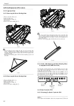
4.4.4.1 Removing the Contact Image Sensor Unit HP
Sensor
0017-7047
1) Remove the left middle cover.
2) Open the feeder cover.
3) Remove the glass retainer [1].
- Screw [2] 3pcs.
4) Remove the stream reading glass [3].
F-4-22
5) Remove the contact image sensor HP sensor [1].
- Connector [2] 1pc.
F-4-23
[2]
[3]
[1]
[2]
[1]
Содержание Laser Class 810
Страница 2: ......
Страница 6: ......
Страница 18: ...Contents...
Страница 19: ...Chapter 1 Introduction...
Страница 20: ......
Страница 22: ......
Страница 55: ...Chapter 1 1 33...
Страница 56: ......
Страница 57: ...Chapter 2 Installation...
Страница 58: ......
Страница 60: ......
Страница 76: ......
Страница 77: ...Chapter 3 Basic Operation...
Страница 78: ......
Страница 80: ......
Страница 87: ...Chapter 3 3 7...
Страница 88: ......
Страница 89: ...Chapter 4 Original Exposure System...
Страница 90: ......
Страница 92: ......
Страница 104: ......
Страница 105: ...Chapter 5 Original Feeding System...
Страница 106: ......
Страница 108: ......
Страница 126: ...Chapter 5 5 18...
Страница 127: ...Chapter 6 Laser Exposure...
Страница 128: ......
Страница 130: ......
Страница 134: ......
Страница 135: ...Chapter 7 Image Formation...
Страница 136: ......
Страница 138: ......
Страница 144: ......
Страница 145: ...Chapter 8 Pickup and Feed System...
Страница 146: ......
Страница 148: ......
Страница 161: ...Chapter 9 Fixing System...
Страница 162: ......
Страница 164: ......
Страница 175: ...Chapter 10 External and Controls...
Страница 176: ......
Страница 180: ...Chapter 10 10 2 F 10 2 FM2000 FM1...
Страница 197: ...Chapter 11 e Maintenance imageWARE Remote...
Страница 198: ......
Страница 200: ......
Страница 210: ......
Страница 211: ...Chapter 12 Maintenance and Inspection...
Страница 212: ......
Страница 214: ......
Страница 216: ......
Страница 217: ...Chapter 13 Measurement and Adjustments...
Страница 218: ......
Страница 220: ......
Страница 226: ......
Страница 227: ...Chapter 14 Correcting Faulty Images...
Страница 228: ......
Страница 230: ......
Страница 236: ...Chapter 14 14 6 F 14 3 12 6 5 11 3 14 1 10 9 8 7 16 13 15 4 2...
Страница 238: ...Chapter 14 14 8...
Страница 239: ...Chapter 15 Error Code...
Страница 240: ......
Страница 242: ......
Страница 249: ...Chapter 16 Service Mode...
Страница 250: ......
Страница 256: ...Chapter 16 16 2...
Страница 304: ......
Страница 305: ...Chapter 17 Upgrading...
Страница 306: ......
Страница 308: ......
Страница 314: ......
Страница 315: ...Chapter 18 Service Tools...
Страница 316: ......
Страница 317: ...Contents Contents 18 1 Service Tools 18 1 18 1 1 Special Tools 18 1...
Страница 318: ......
Страница 320: ......
Страница 321: ...Mar 26 2010...
Страница 322: ......


