


Chapter 10
10-12
piece or two pieces)
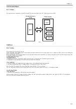
12) Remove the SEND memory [6]. (if equipped with SEND functions)
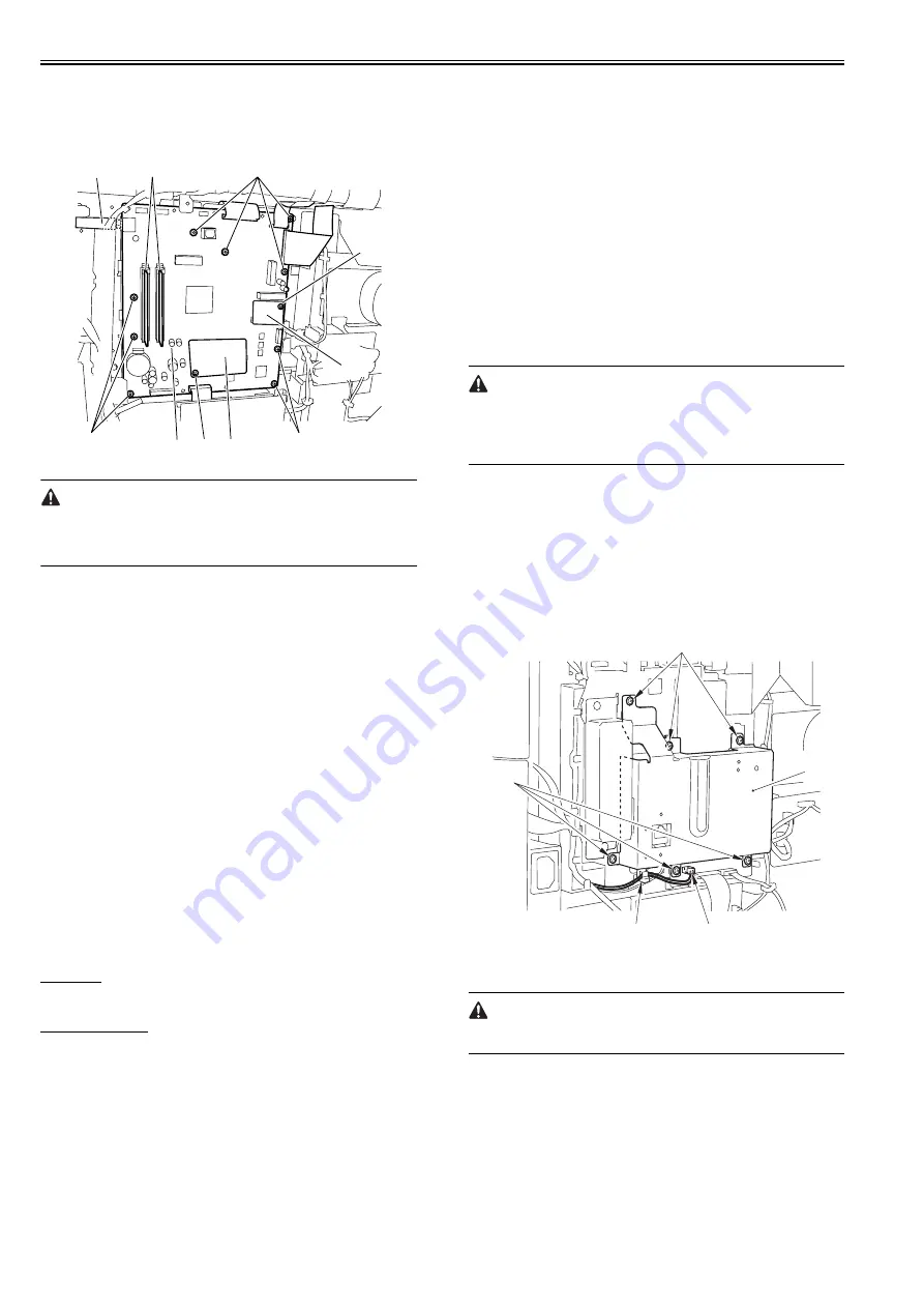
12) Disconnect all connectors and flexible cables from the image processor
PCB.
13) Remove the image processor PCB [7].
- Screw [8] 8pcs.
F-10-28
If the image processor controller PCB must be replaced, be sure to transfer
the following from the old to new PCB:
1. SEND PCB [1] (if equipped with SEND functions)
2. counter PCB [4](if equipped with softcounter functions)
10.4.6.3 Procedure after Replacing the Image Processor
PCB
0017-3631
If you have replaced the image processor PCB with a new one, perform the
following operations:
1. Updating the system software
2. Executing all clear
3. Importing the service data/ user registration data
4. Reading related adjustment
1. Updating the system software
Using the service support tool, download the latest system software (System/
Boot/SEND*1).
*1: if equipped with SEND functions
2. Executing all clear
1) After connecting the power plug to the host machine, turn on the main
power switch.
2) Enter service mode.
Sequentially press the Additional functions key, 2 key, 8 key, and Addi-
tional functions key on the operation panel.
3) Press the arrow key on the touch panel to display "CLEAR".
4) Press the arrow key to display 'ALL', and then press OK. All Clear is ex-
ecuted.(About 40 seconds)
3. Importing the service data/ user registration data
Service data
- Input the all value printed on the service label affixed to the rear cover.
User registration data
1) Press the following keys to enter the USB storage device mode.
"additional functions key" > "01 of the one-touch speed dial key" > "20 of
the one-touch speed dial key" > "view settings key"
2) Display "TURN POWER OFF->ON".
3) Turn off the main power switch, and then turn it on again.
4) Display "USB IMPORT/EXPORT".
5) Start the PC and connect it to this machine with a USB cable.
6) Open My Computer on the PC to check that the "Removable Disk" icon
is displayed.
If the "Removable Disk" icon is not displayed, repeat the above procedure
starting with step 1.
7) Write the user data (address_book.abk and user_data.dat) copied onto the
Desktop as described in "Before Installation (Backup of Data )" over the re-
movable disk.
8) Press the following keys to enter the USB storage device mode.
"additional functions key" > "01 of the one-touch speed dial key" > "20 of
the one-touch speed dial key" > "view settings key"
9) Display "TURN POWER OFF->ON".
10) Close the window on the Desktop.
11) Turn off the main power switch of this machine.
12) Disconnect the USB cable from this machine.
4. Reading related adjustment
- Correction of output between CIS channels
1) Enter the service mode.
Sequentially press the Additional functions key, 2 key, 8 key, and Additional
functions key on the operation panel.
2) Press the arrow key on the touch panel to display "TEST MODE".
3) Press [OK].
4) Press the [2] key to display "SCAN TEST".
5) Press the [1] key to display "SHADING".
6) Press [OK].
After completion of the above procedure, the contact sensor output is com-
pensated and parameters are set automatically.
After completion of automatic adjustment, "OK" is displayed.
Only on image processor PCB system software version WLaa-07-07 of IM-
AGE CLASS 810/i-SENSYS FAX-L3000/FAX-L3000.
If the indicator indicates 'NG' after finishing the auto adjustment, change the
service mode as mentioned below and redo the auto adjustment.
- #SCAN> SCAN SW> SW003> bit6, and change the setting from 1 to 0.
10.4.7 RAM
10.4.7.1 Removing the SDRAM
0017-8973
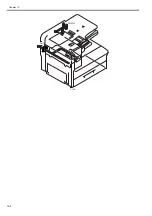
1) Remove the rear cover.
2) Remove the LAN cover [1].
- Connector [2] 1pc.
- Clamp [3] 1pc. (remove the cable.)
- Screw [4] 6pcs.
F-10-29
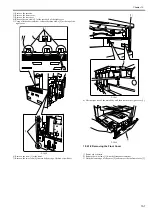
3) Change the position of the jumper plug (JP100) [2] on the modem PCB
[1].
Disconnecting/connecting the modem PCB without this operation may cause
broken SDRAM.
[8]
[5]
[8]
[8]
[7]
[4]
[2]
[1]
[3]
[6]
[1]
[4]
[4]
[2]
[3]
Содержание Laser Class 810
Страница 2: ......
Страница 6: ......
Страница 18: ...Contents...
Страница 19: ...Chapter 1 Introduction...
Страница 20: ......
Страница 22: ......
Страница 55: ...Chapter 1 1 33...
Страница 56: ......
Страница 57: ...Chapter 2 Installation...
Страница 58: ......
Страница 60: ......
Страница 76: ......
Страница 77: ...Chapter 3 Basic Operation...
Страница 78: ......
Страница 80: ......
Страница 87: ...Chapter 3 3 7...
Страница 88: ......
Страница 89: ...Chapter 4 Original Exposure System...
Страница 90: ......
Страница 92: ......
Страница 104: ......
Страница 105: ...Chapter 5 Original Feeding System...
Страница 106: ......
Страница 108: ......
Страница 126: ...Chapter 5 5 18...
Страница 127: ...Chapter 6 Laser Exposure...
Страница 128: ......
Страница 130: ......
Страница 134: ......
Страница 135: ...Chapter 7 Image Formation...
Страница 136: ......
Страница 138: ......
Страница 144: ......
Страница 145: ...Chapter 8 Pickup and Feed System...
Страница 146: ......
Страница 148: ......
Страница 161: ...Chapter 9 Fixing System...
Страница 162: ......
Страница 164: ......
Страница 175: ...Chapter 10 External and Controls...
Страница 176: ......
Страница 180: ...Chapter 10 10 2 F 10 2 FM2000 FM1...
Страница 197: ...Chapter 11 e Maintenance imageWARE Remote...
Страница 198: ......
Страница 200: ......
Страница 210: ......
Страница 211: ...Chapter 12 Maintenance and Inspection...
Страница 212: ......
Страница 214: ......
Страница 216: ......
Страница 217: ...Chapter 13 Measurement and Adjustments...
Страница 218: ......
Страница 220: ......
Страница 226: ......
Страница 227: ...Chapter 14 Correcting Faulty Images...
Страница 228: ......
Страница 230: ......
Страница 236: ...Chapter 14 14 6 F 14 3 12 6 5 11 3 14 1 10 9 8 7 16 13 15 4 2...
Страница 238: ...Chapter 14 14 8...
Страница 239: ...Chapter 15 Error Code...
Страница 240: ......
Страница 242: ......
Страница 249: ...Chapter 16 Service Mode...
Страница 250: ......
Страница 256: ...Chapter 16 16 2...
Страница 304: ......
Страница 305: ...Chapter 17 Upgrading...
Страница 306: ......
Страница 308: ......
Страница 314: ......
Страница 315: ...Chapter 18 Service Tools...
Страница 316: ......
Страница 317: ...Contents Contents 18 1 Service Tools 18 1 18 1 1 Special Tools 18 1...
Страница 318: ......
Страница 320: ......
Страница 321: ...Mar 26 2010...
Страница 322: ......


