3
3-2
Overview
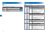
Outline
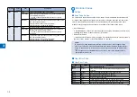
This chapter describes various codes which are displayed when a failure occurs on the
product. These are classified into 3 codes as follows.
Code type
Explanation
Reference
Error code
This code is displayed when an error occurs on the machine.
Jam code
This code is displayed when a jam occurs inside the machine.
Alarm code
This code is displayed when a function of the machine is
malfunctioned.
T-3-1
T-3-1
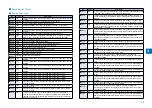
Error Code
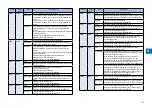
Error Code Details
Ecode
Detail
Code
Item
Description
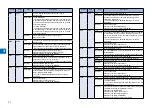
E000
0001
Title
Fixing temperature abnormal rise
Description
The temperature detected by the main thermistor does not
rise to the specified value during startup control.
Remedy
1.Go through the following to clear the error: CLEAR >
ENGIN > ERRCLR; and then turn OFF and then ON the
power.
2.Check connection of the Connectors (Thermistor Connector
and AC Connector).
3.Replace the Fixing Main Thermistor (Film Unit).
4.Replace the Fixing Assembly.
5.Replace the DC Controller PCB (PCB4).
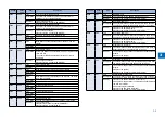
E001
0000
Title
Fixing unit temperature rise detection
Description
The reading of the main thermistor is 250 deg C or more
continuously for 200 msec.
Remedy
1.Go through the following to clear the error: CLEAR >
ENGIN > ERRCLR; and then turn OFF and then ON the
power.
2.Check connection of the Connectors (Thermistor Connector
and AC Connector).
3.Replace the Fixing Main Thermistor (Film Unit).
4.Replace the Fixing Assembly.
5.Replace the DC Controller PCB (PCB4).
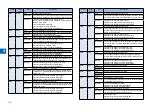
E001
0001
Title
Fixing unit temperature rise detection
Description
The hardware circuit detects overheating of the main or sub
thermistor for 200 msec.
Remedy
1.Go through the following to clear the error: CLEAR >
ENGIN > ERRCLR; and then turn OFF and then ON the
power.
2.Replace the DC Controller PCB (PCB4).
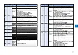
E001
0002
Title
Fixing unit temperature rise detection
Description
The reading of the sub thermistor is 295 deg C or more
continuously for 200 msec.
Remedy
1.Go through the following to clear the error: CLEAR >
ENGIN > ERRCLR; and then turn OFF and then ON the
power.
2.Check connection of the Connectors (Thermistor Connector
and AC Connector).
3.Replace the Fixing Main Thermistor (Film Unit).
4.Replace the Fixing Assembly.
5.Replace the DC Controller PCB (PCB4).
Содержание IMAGERUNNER 2530
Страница 9: ...1 1 Periodical Service Consumable Parts and Cleaning Parts ...
Страница 13: ...1 5 1 Cleaning Parts Fixing guide Transfer guide F 1 2 F 1 2 ...
Страница 14: ...2 2 Adjustment Overview Adjustment when replacing parts image position adjustment ...
Страница 20: ...3 3 Error Code Overview Error Code Jam Code Alarm Code ...
Страница 34: ...4 4 Service Mode Overview Details of Service Mode ...
Страница 85: ...5 5 Parts Replacement and Cleaning List of Parts ...
Страница 98: ...6 6 Product Overview Specifications Product lineups Basic Configuration ...
Страница 106: ...7 7 Version Upgrading Upgrading Targets and Procedure ...

