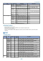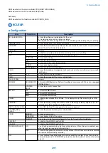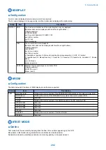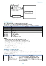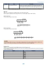
Group
subgroup
Item 1
Explanation
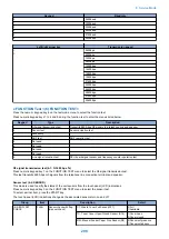
(1) G3 SIGNAL TX TEST 2400bps
(2) G3 SIGNAL TX TEST 4800bps
(3) G3 SIGNAL TX TEST 7200bps
(4) G3 SIGNAL TX TEST 9600bps
(5) G3 SIGNAL TX TEST
TC7200bps
(6) G3 SIGNAL TX TEST
TC9600bps
(7) G3 SIGNAL TX TEST
12000bps
(8) G3 SIGNAL TX TEST
14400bps
(9) G3 SIGNAL TX TEST
TC9600bps
(*) G3 SIGNAL TX TEST 12000bps
(#) G3 SIGNAL TX TEST
14400bps
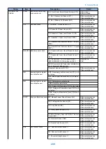
(6) MODEM TEST
Tonal sign reception test
(8) G3 V.34 Tx TEST
V34 G3 signal transmission test
(6) FUNCTION TEST [1] - [9]
(1) FUNCTION TEST G3 4800bps
G3 4800 bps signal transmission test
(2) SENS/SW CHECK
Sensor checks
FLAG
Sensor check with flag
CST
Cassette check
READER
Reader sensor check
A/D
Analog/digital computation output sensor
COPY
Copy confirmation sensor
ADF
ADF sensor check
(3) NCR sts
cardreader test
(9) LINE TEST [1] - [3]
Line signal reception test
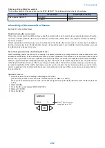
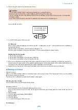
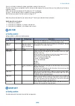
■ Details
● D-RAM Test <(1) D-RAM>
Press the numeric keypad key 1 on the test mode menu to select the D-RAM test.
Press numeric keypad keys 1 and 2 during the D-RAM test to carry out the individual tests described below.
Numeric keypad key 1
Checks to see if data can be correctly written to and read from all areas of D-RAM (SDRAM).
If an error occurs making this check, the test is aborted, with an error appearing on the touch panel (LCD).
Numeric keypad key 2
Checks to see if data can be correctly read from all areas of D-RAM (SDRAM).
If an error occurs making this check, the test is aborted, with an error appearing on the touch panel (LCD).
8. Service Mode
294
Содержание imageRUNNER 2525 Series
Страница 1: ...Revision 9 0 imageRUNNER 2530 2525 2520 Series Service Manual ...
Страница 16: ...Product Overview 1 Product Lineup 7 Features 10 Specifications 11 Name of Parts 15 Operation 18 ...
Страница 62: ...No Part name 3 Laser unit 2 Technical Explanation 52 ...
Страница 119: ...Periodical Service 3 Consumable Parts and Cleaning Parts 110 Cleaning Parts 115 ...
Страница 125: ...Cleaning Parts Fixing guide Transfer guide 3 Periodical Service 115 ...
Страница 136: ...List of Sensors S18 S17 S16 TS2 HU1 S9 S8 S19 TS1 S11 S12 4 Disassembly Assembly 126 ...
Страница 165: ...5 Remove the idler gear 1 claw 1x 4 Disassembly Assembly 155 ...
Страница 172: ... 1 4 2 3 2 2 Remove the scanner motor 4 screws 4x 4 Disassembly Assembly 162 ...
Страница 186: ...3 Remove the RAM PCB Release the hook 4 Disassembly Assembly 176 ...
Страница 187: ...Adjustment 5 Overview 178 Basic Adjustment 180 Adjustment when Replacing the Parts 182 ...
Страница 209: ...Error Jam Alarm 7 Outline 200 Error Code 201 Jam Code 213 Alarm Code 219 ...
Страница 223: ...Jam Code Main Unit 550 sheet 1st cassette model S1 S5 S7 S19 S12 S42 S40 7 Error Jam Alarm 213 ...
Страница 231: ...Service Mode 8 Overview 222 Details of Service Mode 225 Remote UI Service Mode 302 ...
Страница 314: ...Example of report display 8 Service Mode 304 ...
Страница 387: ...APPENDICES Service Tools 378 General Circuit Diagram 379 ...

