NOTE:
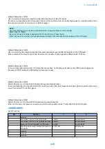
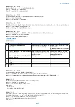
Any of the following error codes may be indicated at time of transmission because of the line condition:
##100, ##101, ##102, ##104, ##201, ##280, ##281, ##282, ##283, ##284, ##750,
##752, ##754, ##755, ##757, ##759, ##760, ##762, ##764, ##765,
##767, ##769, ##770, ##772, ##774, ##775, ##777, ##779, ##780, ##782, ##784,
##785, ##787, ##789
Any of the following error codes may be indicated at time of reception because of the line condition:
##103, ##106, ##107, ##201, ##793
##103, ##106, ##107, ##201, ##793
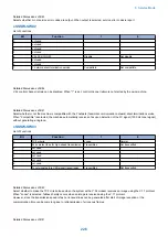
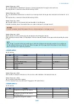
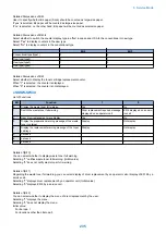
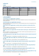
● 008: V.34 modulation speed upper limit
Use it to set an upper limit to the modulation speed (baud rate) for the V.34 primary channel.
● 009: V.34 data speed upper limit
Use it to set an upper limit to the data transmission speed for the V.34 primary channel between 2.4K and 33.6K bps in increments
of 2400 bps. (0: 2.4K to 13:33.6K bps).
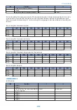
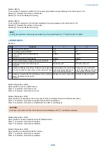
● 010: Frequency of the pseudo CI signal
You may select a frequency for the pseudo CI signal.
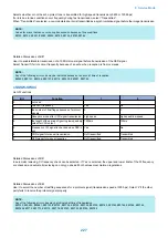
Some types of external telephones do not ring when the fax/tel switch-over function is ON.
To sound the ring, change the pseudo CI signal
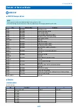
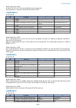
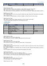
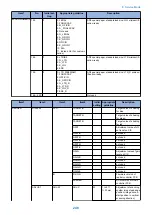
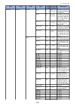
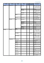
#NUMERIC
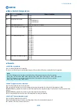
■ Numerical Parameter Composition
No.
Item
Range of settings
002
RTN transmission condition(1)
1% to 99%
003
RTN transmission condition (2)
2 to 99 item
004
RTN transmission condition (3)
1 to 99 lines
005
NCC pause time length (pre-ID code)
1 to 60 sec
006
NCC pause time length (post-ID code)
1 to 60 sec
008
Time from Right After Dialing by Auto-dialing to Start of Communication 1 to 65 sec
010
line condition identification time length
0 to 9999 (10 msec)
011
T.30T1 timer (for reception)
0 to 9999 (10 msec)
012
The maximum number of received lines
0 to 65535 (line) * Unlimited in the case of 0
013
T.30 EOL timer
500 to 3000 (10 msec)
015
hooking detection time length
0 to 999
016
time length to first response at time of fax/tel switchover
0 to 9
017
pseudo RBT signal pattern ON time length
0 to 999
018
pseudo RBT signal pattern OFF time length (short)
0 to 999
019
pseudo RBT signal pattern OFF time length (long)
0 to 999
020
pseudo CI signal pattern ON time length
0 to 999
021
pseudo CI signal pattern OFF time length (short)
0 to 999
022
pseudo CI signal pattern OFF time length (long)
0 to 999
023
CNG detection level at time of fax/tel switchover
0 to 7
024
pseudo RBT transmission level at time of fax/tel switchover
10 to 20
0 to 20 (120/230V)
025
Answering machine connection function signal detection time
0 to 999
027
preamble detection time length for V21 low-speed flag
20 (x 10ms)
051
Hooking detection threshold
0 to 655035
053
Setting of DTMF call origination count at remote reception of fax
0 to 65535 (25 counts)
054
Setting of busy tone output time when handset is used
0 to 480 (60min) (0: no data acquisition)
055
acquisition period of environmental log data
0 to 480 (60min)
056
display the type of soft counter 1
101 (Fixed)
8. Service Mode
239
Содержание imageRUNNER 2525 Series
Страница 1: ...Revision 9 0 imageRUNNER 2530 2525 2520 Series Service Manual ...
Страница 16: ...Product Overview 1 Product Lineup 7 Features 10 Specifications 11 Name of Parts 15 Operation 18 ...
Страница 62: ...No Part name 3 Laser unit 2 Technical Explanation 52 ...
Страница 119: ...Periodical Service 3 Consumable Parts and Cleaning Parts 110 Cleaning Parts 115 ...
Страница 125: ...Cleaning Parts Fixing guide Transfer guide 3 Periodical Service 115 ...
Страница 136: ...List of Sensors S18 S17 S16 TS2 HU1 S9 S8 S19 TS1 S11 S12 4 Disassembly Assembly 126 ...
Страница 165: ...5 Remove the idler gear 1 claw 1x 4 Disassembly Assembly 155 ...
Страница 172: ... 1 4 2 3 2 2 Remove the scanner motor 4 screws 4x 4 Disassembly Assembly 162 ...
Страница 186: ...3 Remove the RAM PCB Release the hook 4 Disassembly Assembly 176 ...
Страница 187: ...Adjustment 5 Overview 178 Basic Adjustment 180 Adjustment when Replacing the Parts 182 ...
Страница 209: ...Error Jam Alarm 7 Outline 200 Error Code 201 Jam Code 213 Alarm Code 219 ...
Страница 223: ...Jam Code Main Unit 550 sheet 1st cassette model S1 S5 S7 S19 S12 S42 S40 7 Error Jam Alarm 213 ...
Страница 231: ...Service Mode 8 Overview 222 Details of Service Mode 225 Remote UI Service Mode 302 ...
Страница 314: ...Example of report display 8 Service Mode 304 ...
Страница 387: ...APPENDICES Service Tools 378 General Circuit Diagram 379 ...

