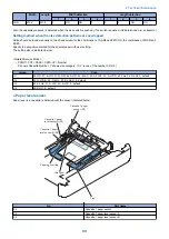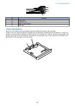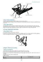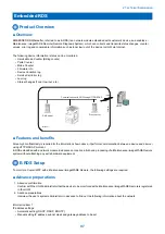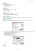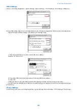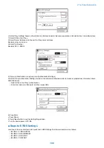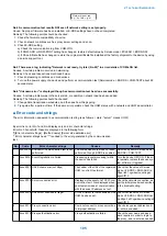
b. Select #E-RDS SWITCH,and set value "1" then touch [OK].
The communication with UGW is enabled by the above setting.
• 0 : OFF( initial value): e-Maintenance/ imageWARE Remote is disabled.
• 1 : ON: e-Maintenance/ imageWARE Remote is enabled
CAUTION:
The following settings i.e. RGW-PORT and RGW-ADR in servicemode must not be change unless there are specific
instructions to do so. Changing these values will cause error in communication with UGW.
c. Select COM-TEST and then touch [OK]. This initiates the communication test between the device and the UGW. If the
communication is successful, OK is displayed. If NG (failed) appears, refer to the troubleshooting guide and repeat until OK! is
displayed.
NOTE:
The communication results with UGW can be distinguished by referring to the communication log. By performing the
communication test with UGW, E-RDS acquires schedule information and starts monitoring and meter reads operation.
■ Communication log
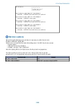
(1) COM-LOG
• #E-RDS COM-LOG
Move on to COM-TEST by using Left/ Right allow key.
The maximum 5 records logged
Only for the head portion of the error details written on COM-LOG is displayed.
(2) Details of communication log
You can use communication log to verify that a detailed error code SOAP method name, etc. are displayed at the time of
communication test failure.
• By pressing ? key or OK key, progressive information (generating date/ time of error) is displayed.
• Error details will be displayed when OK key is again pressed in the state line where generating time is displayed.
Error information: within maximum 128 character strings (NULL is not included).
Refer to the error list for the message strings displayed on the COM-LOG.
■ Initializing E-RDS settings
It is possible to return E-RDS Settings to factory-shipments value.
1) Select #CLEAR ERDS-DAT by using Left/ Right allow key.
2) When [OK] is touched, a confirmation message "OK?" is displayed.
3) If agree upon initialization, following E-RDS settings, internal data, and Alarm filtering information will be purged.
• #E-RDS > E-RDS SWITCH
• #E-RDS > RGW-ADDRESS
• #E-RDS > RGW-PORT
• #E-RDS > COM-LOG
CAUTION:
In case of replacing the CA certificate file, even #CLEAR is executed, the status is not returned to the factory default.
When installing the certificate file other than the factory default CA certificate file, it is required to delete the certificate file
after E-RDS initialization and install the factory default CA certificate file.
2. Technical Explanation
102
Содержание imageRUNNER 2525 Series
Страница 1: ...Revision 9 0 imageRUNNER 2530 2525 2520 Series Service Manual ...
Страница 16: ...Product Overview 1 Product Lineup 7 Features 10 Specifications 11 Name of Parts 15 Operation 18 ...
Страница 62: ...No Part name 3 Laser unit 2 Technical Explanation 52 ...
Страница 119: ...Periodical Service 3 Consumable Parts and Cleaning Parts 110 Cleaning Parts 115 ...
Страница 125: ...Cleaning Parts Fixing guide Transfer guide 3 Periodical Service 115 ...
Страница 136: ...List of Sensors S18 S17 S16 TS2 HU1 S9 S8 S19 TS1 S11 S12 4 Disassembly Assembly 126 ...
Страница 165: ...5 Remove the idler gear 1 claw 1x 4 Disassembly Assembly 155 ...
Страница 172: ... 1 4 2 3 2 2 Remove the scanner motor 4 screws 4x 4 Disassembly Assembly 162 ...
Страница 186: ...3 Remove the RAM PCB Release the hook 4 Disassembly Assembly 176 ...
Страница 187: ...Adjustment 5 Overview 178 Basic Adjustment 180 Adjustment when Replacing the Parts 182 ...
Страница 209: ...Error Jam Alarm 7 Outline 200 Error Code 201 Jam Code 213 Alarm Code 219 ...
Страница 223: ...Jam Code Main Unit 550 sheet 1st cassette model S1 S5 S7 S19 S12 S42 S40 7 Error Jam Alarm 213 ...
Страница 231: ...Service Mode 8 Overview 222 Details of Service Mode 225 Remote UI Service Mode 302 ...
Страница 314: ...Example of report display 8 Service Mode 304 ...
Страница 387: ...APPENDICES Service Tools 378 General Circuit Diagram 379 ...


