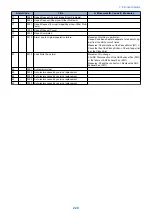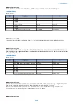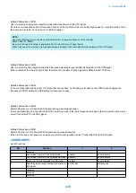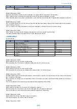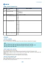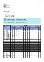
Selects whether or not the echo protect tone is transmitted for high-speed transmission (9600 or 7200 bps).
If errors due to line conditions occur frequently during fax transmission, select “Transmitted”.
When “Transmitted” is selected, a non-modulated carrier is transmitted as a synchronization signal before the image transmission.
NOTE:
Codes for errors that can occur during transmission because of line conditions:
##100, ##104, ##281, ##282, ##283, ##750, ##755, ##760,##765
Detailed Discussions of Bit 7
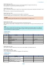
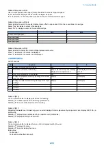
Use it to enable/disable transmission of a 1080-Hz tonal signal before transmission of the CED signal.
Select 'transmit' if errors occur frequently because of an echo when reception is from overseas.
NOTE:
Any of the following error code may be indicated because of an echo at time of reception
##0005, ##0101, ##0106, ##0107, ##0114, ##0200, ##0201, ##0790
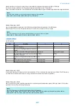
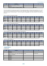
● SSSW-SW04
List of Functions
Bit
Function
1
0
0
not used
-
-
1
Check CI frequency
Yes
No
2
the number of final flag sequences of protocol
signals
2
1
3
Reception mode after CFR signal transmission
high speed
high speed/low speed
4
the length of the period of ignoring low speed sig-
nals after CFR output
1500ms
700ms
5
Frequency of CI signal is checked when PBX is
set.
Yes
No
6
CNG signal for manual transmission
Not transmitted
Transmitted
7
CED signal for manual reception
Not transmitted
Transmitted
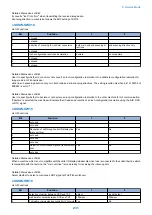
Detailed Discussions of Bit 1
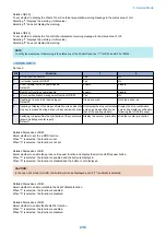
In automatic recieving, CI frequency check can be selected. If ‘Yes’ is selected, the upper and lower limits of the CI frequency
are checked, and automatic recieving can only go ahead if both values meet German regulations.
Detailed Discussions of Bit 2
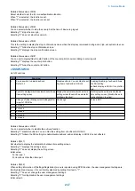
Use it to select the number of last flag sequences for a protocol signal (transmission speed at 300 bps). Select '2' if the other
party fails to receive the protocol signal properly.
NOTE:
Any of the following error codes may be indicated at time of transmission
##0100, ##0280, ##0281, ##0750, ##0753, ##0754, ##0755, ##0758, ##0759, ##0760, ##0763 ##0764, ##0765, ##0768,
##0769,##0770, ##0773, ##0775, ##0778, ##0780, ##0783, ##0785, ##0788
8. Service Mode
227
Содержание imageRUNNER 2525 Series
Страница 1: ...Revision 9 0 imageRUNNER 2530 2525 2520 Series Service Manual ...
Страница 16: ...Product Overview 1 Product Lineup 7 Features 10 Specifications 11 Name of Parts 15 Operation 18 ...
Страница 62: ...No Part name 3 Laser unit 2 Technical Explanation 52 ...
Страница 119: ...Periodical Service 3 Consumable Parts and Cleaning Parts 110 Cleaning Parts 115 ...
Страница 125: ...Cleaning Parts Fixing guide Transfer guide 3 Periodical Service 115 ...
Страница 136: ...List of Sensors S18 S17 S16 TS2 HU1 S9 S8 S19 TS1 S11 S12 4 Disassembly Assembly 126 ...
Страница 165: ...5 Remove the idler gear 1 claw 1x 4 Disassembly Assembly 155 ...
Страница 172: ... 1 4 2 3 2 2 Remove the scanner motor 4 screws 4x 4 Disassembly Assembly 162 ...
Страница 186: ...3 Remove the RAM PCB Release the hook 4 Disassembly Assembly 176 ...
Страница 187: ...Adjustment 5 Overview 178 Basic Adjustment 180 Adjustment when Replacing the Parts 182 ...
Страница 209: ...Error Jam Alarm 7 Outline 200 Error Code 201 Jam Code 213 Alarm Code 219 ...
Страница 223: ...Jam Code Main Unit 550 sheet 1st cassette model S1 S5 S7 S19 S12 S42 S40 7 Error Jam Alarm 213 ...
Страница 231: ...Service Mode 8 Overview 222 Details of Service Mode 225 Remote UI Service Mode 302 ...
Страница 314: ...Example of report display 8 Service Mode 304 ...
Страница 387: ...APPENDICES Service Tools 378 General Circuit Diagram 379 ...


