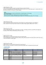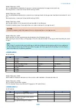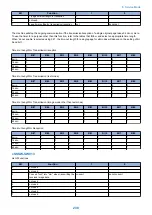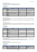
Details of Service Mode
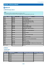
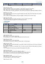
#SSSW
■ SSSW Composition
NOTE:
This document describes the default settings for the system for USA.
The default settings used in the service mode vary depending on the shipping destination and model.
No.
Initial setting
Function
SW01
00000000
error/copy control
SW02
00010000
network connection setting
SW03
00000000
echo remedy setting
SW04
00000000
communication fault remedy setting
SW05
00000000
standard function (DIS signal) setting
SW06
10010000
read condition setting
SW7-SW11
not used
SW12
00000010
page timer setting
SW13
00000000
meter/inch resolution setting
SW14
00000001
inch/meter resolution setting
SW15
00000000
dial-in FAX/TEL switch-over function
SW16-17
not used
SW18
00000000
remedies for communication faults (2)
SW19-21
not used
SW22
00000000
fault remedy setting
SW23-24
not used
SW25
00000000
report indication resolution setting
SW26-27
not used
SW28
00000000
V.8/V.34 protocol settings
SW29
not used
SW30
00000000
Assigning a New Dial Tone Detection Method
SW31
not used
SW32
00000000
NCU version setting
SW33
00000000
counter function settings
SW34
00011011
waste toner container/toner cartridge/drum unit display settings
SW35
00001000
e-RDS function settings
SW36 - SW50
not used
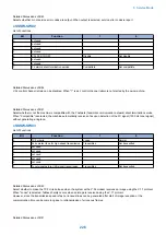
■ Details
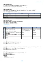
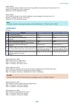
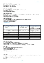
● SSSW-SW01
List of Functions
Bit
Function
1
0
0
service error code
output
not output
1
not used
-
-
2
not used
-
-
3
not used
-
-
4
not used
-
-
5
not used
-
-
6
not used
-
-
7
not used
-
-
8. Service Mode
225
Содержание imageRUNNER 2525 Series
Страница 1: ...Revision 9 0 imageRUNNER 2530 2525 2520 Series Service Manual ...
Страница 16: ...Product Overview 1 Product Lineup 7 Features 10 Specifications 11 Name of Parts 15 Operation 18 ...
Страница 62: ...No Part name 3 Laser unit 2 Technical Explanation 52 ...
Страница 119: ...Periodical Service 3 Consumable Parts and Cleaning Parts 110 Cleaning Parts 115 ...
Страница 125: ...Cleaning Parts Fixing guide Transfer guide 3 Periodical Service 115 ...
Страница 136: ...List of Sensors S18 S17 S16 TS2 HU1 S9 S8 S19 TS1 S11 S12 4 Disassembly Assembly 126 ...
Страница 165: ...5 Remove the idler gear 1 claw 1x 4 Disassembly Assembly 155 ...
Страница 172: ... 1 4 2 3 2 2 Remove the scanner motor 4 screws 4x 4 Disassembly Assembly 162 ...
Страница 186: ...3 Remove the RAM PCB Release the hook 4 Disassembly Assembly 176 ...
Страница 187: ...Adjustment 5 Overview 178 Basic Adjustment 180 Adjustment when Replacing the Parts 182 ...
Страница 209: ...Error Jam Alarm 7 Outline 200 Error Code 201 Jam Code 213 Alarm Code 219 ...
Страница 223: ...Jam Code Main Unit 550 sheet 1st cassette model S1 S5 S7 S19 S12 S42 S40 7 Error Jam Alarm 213 ...
Страница 231: ...Service Mode 8 Overview 222 Details of Service Mode 225 Remote UI Service Mode 302 ...
Страница 314: ...Example of report display 8 Service Mode 304 ...
Страница 387: ...APPENDICES Service Tools 378 General Circuit Diagram 379 ...


