Adjustment when Replacing the Parts
Original Exposure
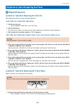
■ Action to Take after Replacing the CIS Unit
After replacing the CIS unit, make the following adjustments:
● CIS white level automatic adjustment
1. Enter the service mode.
• SCAN > READER > FUNCTION > CCD > CCD-ADJ
2. Click the [OK] button.
When this step is complete, the contact sensor output is adjusted and parameters are set automatically.
3. After completion of automatic adjustment, “OK” is displayed.
● DF white level adjustment (platen board cover scan/stream reading scan)
CAUTION:
Make this adjustment when the DADF is installed.
1. Place a sheet of paper that the user usually uses on the platen glass, enter the service mode, and then select SCAN
> READER > FUNCTION > CCD > DFWLVL1.
Read the white level in the BOOK mode. (Check the transparency of the glass for BOOK mode.)
2. Place a sheet of paper that the user usually uses on the DF, enter the service mode, and then select SCAN > READER
> FUNCTION > CCD > DF-WLVL2.
Read the white level in the DF mode (stream reading). (Check the transparency of the glass for stream reading.)(Read both
sides of the chart.)
3. Place a sheet of paper that the user usually uses on the platen glass, enter the service mode, and then select SCAN
> READER > FUNCTION > CCD > DFWLVL3.
Read the white level in the BOOK mode. (Check the transparency of the glass for BOOK mode.)
4. Place a sheet of paper that the user usually uses on the DF, enter the service mode, and then select SCAN > READER
> FUNCTION > CCD > DF-WLVL4.
Read the white level in the DF mode (stream reading). (Check the transparency of the glass for stream reading.)(Read both
sides of the chart.)
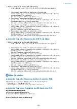
■ Action to Take after Replacing the Platen Glass
Enter the service mode, and then select the following:
CAUTION:
Be sure to make the white plate data adjustment before ADF white level adjustment.
W-PLT-X
W-PLT-Y
W-PLT-Z
1. Enter the value indicated on the platen glass in the following service mode:
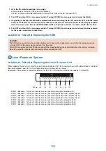
• SCAN > READER > ADJUST > CCD > W-PLT-X/Y/Z (Input of standard white plate data)
5. Adjustment
182
Содержание imageRUNNER 2525 Series
Страница 1: ...Revision 9 0 imageRUNNER 2530 2525 2520 Series Service Manual ...
Страница 16: ...Product Overview 1 Product Lineup 7 Features 10 Specifications 11 Name of Parts 15 Operation 18 ...
Страница 62: ...No Part name 3 Laser unit 2 Technical Explanation 52 ...
Страница 119: ...Periodical Service 3 Consumable Parts and Cleaning Parts 110 Cleaning Parts 115 ...
Страница 125: ...Cleaning Parts Fixing guide Transfer guide 3 Periodical Service 115 ...
Страница 136: ...List of Sensors S18 S17 S16 TS2 HU1 S9 S8 S19 TS1 S11 S12 4 Disassembly Assembly 126 ...
Страница 165: ...5 Remove the idler gear 1 claw 1x 4 Disassembly Assembly 155 ...
Страница 172: ... 1 4 2 3 2 2 Remove the scanner motor 4 screws 4x 4 Disassembly Assembly 162 ...
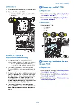
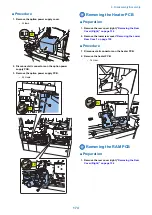
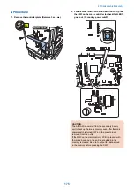
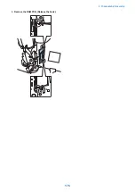
Страница 186: ...3 Remove the RAM PCB Release the hook 4 Disassembly Assembly 176 ...
Страница 187: ...Adjustment 5 Overview 178 Basic Adjustment 180 Adjustment when Replacing the Parts 182 ...
Страница 209: ...Error Jam Alarm 7 Outline 200 Error Code 201 Jam Code 213 Alarm Code 219 ...
Страница 223: ...Jam Code Main Unit 550 sheet 1st cassette model S1 S5 S7 S19 S12 S42 S40 7 Error Jam Alarm 213 ...
Страница 231: ...Service Mode 8 Overview 222 Details of Service Mode 225 Remote UI Service Mode 302 ...
Страница 314: ...Example of report display 8 Service Mode 304 ...
Страница 387: ...APPENDICES Service Tools 378 General Circuit Diagram 379 ...

