1
2
3
4
5
6
7
8
9
10
1
2
3
4
5
6
7
8
9
10
F
E
D
C
B
A
F
E
D
C
B
A
P.6
USB(H)
J8103
J8110
SDcard
J8104
USB(D)
J8111
LAN
Mi
2
Ba
tt
e
ry
(+
)
(-
)
Se
co
n
d
a
ry
J8124
1
2
N.
C
.
G
N
D
20
22
21
19
18
17
16
15
14
13
12
11
10
9
8
7
6
5
4
3
2
G
N
D
G
N
D
VH(+)
AG
ND
+12V
SNO
OP
TX_O
UT
RX_I
N
2
3
4
5
6
7
8
9
10
11
12
13
14
15
16
17
18
19
20
21
22
J1
+5V
G
N
D
+3.
3V
CI
VS
DCL
IM
SRD
PRD
HRD
CMLD
LPRD
CI
1
CI
2
N.
C
.
HOO
K1
HOO
K2
CAI
DD
LPL1
LPL2
IPSEL
N.
C
.
+5V
1
VH(-)
CT1
CT2
T2
N.C.
L1
L2
T1
1
1
2
GND
GND
GND
CARD_READER_RX
CARD_READER_TX
CARD_READER_COUNT
+5V
B_CRDY
C_CRDY
B_PRDY
C_PRDY
COIN_TX
COIN_RX
VOUT1
VOUT2
GND
VCC(5Vor3.3V)
GND
GND
CCVI_OPTION
CCVI_CL_BW_L
CCVI_KYU_COUNT
CCVI_CP_ENB
+5V
J8
14
9
J8103
Mi
2
GND
CCVI_LARGE_SMALL_B
J2
USB(H)
USB
CI
C
NT_O
UT
+24V
G
N
D
FFC
J8127
+24V
2
1
J8134
1
2
3
4
J001
2
1
J002
1
1
1
0
9
8
2
3
4
5
6
1
7
J00
02
1
2
3
4
5
6
7
J9
9
0
4
1
2
3
4
5
6
7
J8
1
1
7
1
2
J81
40
2
1
SP1
9
8
2
3
4
5
6
1
7
J8
1
1
8
1
2
3
4
5
J9
9
0
1
1
2
3
4
5
J8
1
1
9
1
2
3
J8146
1
2
3
4
5
6
7
J00
4
1
2
3
4
5
6
J8147
1
2
3
4
5
6
J02
1
2
3
4
5
6
7
J3
2
1
J4
2
3
1
J00
3
2
1
J9999
2
1
J112
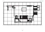
MODEM PCB
Modular
PCB
NCU PCB
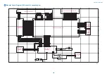
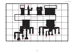
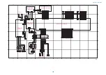
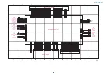
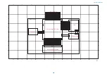
Main Controller PCB (3/3)
Speaker (Option)
to Power Supply PCB
Card Reader
to Coin Vendor
Control Interface
Cable
USB hub PCB
FAX BOX
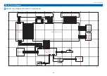
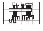
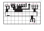
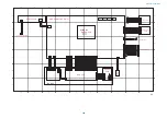
General Circuit Diagram
391
Содержание imageRUNNER 2525 Series
Страница 1: ...Revision 9 0 imageRUNNER 2530 2525 2520 Series Service Manual ...
Страница 16: ...Product Overview 1 Product Lineup 7 Features 10 Specifications 11 Name of Parts 15 Operation 18 ...
Страница 62: ...No Part name 3 Laser unit 2 Technical Explanation 52 ...
Страница 119: ...Periodical Service 3 Consumable Parts and Cleaning Parts 110 Cleaning Parts 115 ...
Страница 125: ...Cleaning Parts Fixing guide Transfer guide 3 Periodical Service 115 ...
Страница 136: ...List of Sensors S18 S17 S16 TS2 HU1 S9 S8 S19 TS1 S11 S12 4 Disassembly Assembly 126 ...
Страница 165: ...5 Remove the idler gear 1 claw 1x 4 Disassembly Assembly 155 ...
Страница 172: ... 1 4 2 3 2 2 Remove the scanner motor 4 screws 4x 4 Disassembly Assembly 162 ...
Страница 186: ...3 Remove the RAM PCB Release the hook 4 Disassembly Assembly 176 ...
Страница 187: ...Adjustment 5 Overview 178 Basic Adjustment 180 Adjustment when Replacing the Parts 182 ...
Страница 209: ...Error Jam Alarm 7 Outline 200 Error Code 201 Jam Code 213 Alarm Code 219 ...
Страница 223: ...Jam Code Main Unit 550 sheet 1st cassette model S1 S5 S7 S19 S12 S42 S40 7 Error Jam Alarm 213 ...
Страница 231: ...Service Mode 8 Overview 222 Details of Service Mode 225 Remote UI Service Mode 302 ...
Страница 314: ...Example of report display 8 Service Mode 304 ...
Страница 387: ...APPENDICES Service Tools 378 General Circuit Diagram 379 ...


