Chapter 1: Product description Wireless
operation
Page 1-16
The 5ms frame period configuration provides higher throughput as a result of reduced frame
overhead during transmission. In turn, the 2.5 ms frame period configuration affords reduced
latency in the system, half of that introduced by the 5 ms frame configuration.
Frame configuration - Downlink Data
The percentage of frame assigned to transport downlink data. The downlink data specifies the
percentage of the aggregate throughput for the downlink (frames transmitted from the AP/BHM to
the subscriber). The configurable range is 15 to 85 percent.
Link operation – Dynamic Rate Adapt
The 450 Platform Family ODUs offer eight levels or speeds of operation – 2X MIMO-B and 1X
MIMO-A (QPSK), 4X MIMO-B and 2X MIMO-A (16-QAM), 6x MIMO-B and 3X MIMO-A (64-QAM)
and 8X MIMO-B and 4X MIMO-A (265-QAM). If received power varies due to distance between the
AP/BHM and the SM/BHS or due to obstructions, or if interference affects the RF environment, the
system automatically and dynamically adjusts the links to the best operation level.
The system chooses its modulation rate dynamically, based on an internal ARQ (Automatic Repeat
reQuest) error control method. With ARQ, every data slot of every frame sent over the air (except
downlink broadcast) is expected to be acknowledged by the receiver, and if acknowledgement is
not received, the data is resent. The sending unit monitors these re-sends and adjusts the
modulation rate accordingly. It is normal to have links that change levels of operation as the RF
environment changes. Furthermore, the uplink or downlink portions of TDD duty cycle operate
independently.
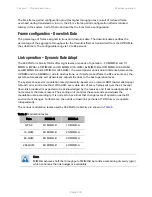
The various modulation levels used by 450 Platform Family are shown in
Table 9
.
Table 9 Modulation levels
Rate
MIMO-B
MIMO-A
QPSK 2X
MIMO-B 1X
MIMO-A
16-QAM 4X
MIMO-B 2X
MIMO-A
64-QAM 6X
MIMO-B 3X
MIMO-A
256-QAM 8X
MIMO-B 4X
MIMO-A
Note
MIMO-A achieves half the throughput of MIMO-B but adds a combining diversity (gain)
which enhances the link budget or availability.
Содержание PMP 450d Series
Страница 101: ...Chapter 2 System hardware GPS synchronization Page 2 40 Figure 25 Cluster Management Scenario 1 ...
Страница 125: ...Chapter 3 System planning Typical deployment Page 3 3 Figure 37 Wall installation ...
Страница 126: ...Chapter 3 System planning Typical deployment Page 3 4 Figure 38 Roof installation ...
Страница 127: ...Chapter 3 System planning Typical deployment Page 3 5 Figure 39 GPS receiver wall installation ...
Страница 128: ...Chapter 3 System planning Typical deployment Page 3 6 Figure 40 GPS receiver tower or mast installation ...


