background image

Document type:

Title:

Revision date:

Revision:

User's Manual (MUT)

Mod. SY2527, Universal Multichannel Power Supply System

27/11/2000

0

NPO:

Filename:

Number of pages:

Page:

00103/97:2527y.MUTx/00

SY2527USERMANUAL_REV0.DOC

84

7

1. About this manual

The purpose of this guide is to illustrate:


the several parameters and commands available for the control and status
monitoring of the SY2527 Universal Multichannel Power Supply System and of
the board channels,


the requirements and instructions for its correct operation in different hardware
configurations,


the

 User Software Interface 

used to control the system interactively.

The preliminary section of the guide starts with a short description of the SY2527 system
with a summary of its main features and performances.

The core of the guide consists of two sections:
a reference section with a detailed description of the commands, alarms and parameters
which allow for the control and monitoring of the system and of the board channels;
a second section which illustrates the operating modes of the SY2527 system for
different hardware configurations for interactive control of the system, paying particular
attention to the 

User Software Interface

 for standalone and terminal operation.

A detailed description of all hardware components and system installation instructions
can be found in the 

Hardware Installation Guide

.

Содержание SY 2527

Страница 1: ...User s Manual MOD SY 2527 27 November 2000 Revision n 0 UNIVERSAL MULTICHANNEL POWER SUPPLY SYSTEM USER S MANUAL NPO 00103 97 2527y MUTx 00...

Страница 2: ...GENERAL INFORMATION 18 3 1 1 Injury Precautions 18 3 1 2 Product Damage Precautions 19 3 1 3 EC Certifications and Compliance 19 3 1 4 Terms in this Manual 19 3 2 SAFETY TERMS AND SYMBOLS ON THE PROD...

Страница 3: ...R PW 31 4 4 15 POWER ON POn 32 4 4 16 POWER DOWN PDwn 32 4 5 CHANNEL STATUS 32 4 6 BOARD STATUS 33 5 SYSTEM POWER ON 34 5 1 PRELIMINARY CHECK 34 5 2 LOCAL POWER ON 34 5 3 REMOTE POWER ON 35 6 CONFIGUR...

Страница 4: ...SETUP Menu Communications 68 7 1 24 The SETUP Menu Security 68 7 1 25 The SETUP Menu Log Options 68 7 1 26 The SETUP Menu Tech Info 69 7 1 27 The SETUP Menu HV Clock Conf 69 7 2 REMOTE OPERATION VIA T...

Страница 5: ...IN STANDALONE OPERATION 43 FIG 7 3 WELCOME SCREEN IN STANDALONE OPERATION 44 FIG 7 4 LOGIN WINDOW 45 FIG 7 5 START UP WINDOW 46 FIG 7 6 ABOUT WINDOW 47 FIG 7 7 SESSION WINDOW 48 FIG 7 8 CHANNELS WIND...

Страница 6: ...E 2 2 TECHNICAL SPECIFICATIONS OF THE SY2527 MAINFRAME FRONT AND REAR PANEL COMPONENTS 16 TABLE 2 3 TECHNICAL SPECIFICATIONS OF THE SY2527 MAINFRAME INPUT AND OUTPUT SIGNALS 17 TABLE 6 1 RS232 PORT DE...

Страница 7: ...o control the system interactively The preliminary section of the guide starts with a short description of the SY2527 system with a summary of its main features and performances The core of the guide...

Страница 8: ...er 5 System Power On it contains the procedure for the power on of the system together with a first check of its correct operation Chapter 6 Configuring the interfaces it contains the procedure for th...

Страница 9: ...y or loss of life CAUTION Caution statements identify conditions or practices that could result in damage to this product or other property Please pay particular attention to the grey areas where warn...

Страница 10: ...boards with different functions such as High Low Voltage boards generic I O boards temperature pressure monitors etc and branch controllers where the latter are used to control other remote generator...

Страница 11: ...h branch controller thanks to the use of one microprocessor per slot All the operational parameters are stored in a non volatile memory EEPROM to be still available after Power Off The parameters can...

Страница 12: ...stom status displays and other features designed to help the management of a large number of channels Programmable parameters for each power channel include two voltage values V0set V1set and two curr...

Страница 13: ...ly from the Ramp Down parameter set For a detailed description of all system control and monitoring signals and of channel parameters please refer to Section 4 in this manual In order to protect the S...

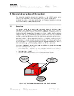
Страница 14: ...Board Slot 5 I O Board CPU Front Panel LCD Screen 1 2 3 4 5 6 7 8 9 0 ACK CMD BS Contrast Brightness Keyboard Compact Switch Input Output Expansion Slots I O Controller of Keyboard Compact Switch LCD...

Страница 15: ...es Table 2 1 Technical specifications of the SY2527 mainframe general Packaging 19 wide 4U high Euro mechanics rack Depth 770 mm Weight Mainframe 19 kg Power Requirements Monophase 88 264 V a c 48 64...

Страница 16: ...respectively occurs INTERLOCK red LED lights up as the system is in INTERLOCK condition LOCAL NET CAENET red LEDs light up as the relevant connectors are in activity MASTER red LED lights up as the H...

Страница 17: ...00 type LEMO connector Function at least one channel is in Under Voltage OVV Std NIM TTL selectable 00 type LEMO connector Function at least one channel is in Over Voltage CH ON Std NIM TTL selectabl...

Страница 18: ...Avoid Electric Overload To avoid electric shock or fire hazard do not apply a voltage to a load that is outside the range specified for that load Avoid Electric Shock To avoid injury or loss of life d...

Страница 19: ...ient cooling and mains connection must be secured according to regulations Signal lines length during all tests was less than 3 m The RS232 cable must be properly shielded and have a length of less th...

Страница 20: ...Supply System 27 11 2000 0 NPO Filename Number of pages Page 00103 97 2527y MUTx 00 SY2527USERMANUAL_REV0 DOC 84 20 3 3 General Operation Requirements Before operation check the following requirement...

Страница 21: ...onitoring of the channels of the board communication with the system CPU The following sections contain an overview of the commands parameters and alarms for the control and monitoring of the system a...

Страница 22: ...occur by sending a proper REMOTE IN input signal through the relevant connector The REMOTE IN input signal see Fig 5 1 for the connector location on the front panel must be a 12 V input level 50 mA m...

Страница 23: ...e V1SET LED ON When channels are switched from V0SET to V1SET or vice versa the output voltage drifts from one value to the other at the rate programmed for each channel Ramp Up or Ramp Down parameter...

Страница 24: ...the channels will be off independently from the condition in which they were before the RESET N B please note that any type of reset command must be enabled via software in the RESET FLAG window by ta...

Страница 25: ...RATE GROUND For further details on electro mechanical specifications of the components please refer to the Technical Specifications Section in the Hardware Installation Guide A short summary of all fr...

Страница 26: ...urs when at least one channel is in Over Voltage condition i e when the actual value of the channel output voltage is higher than the programmed value The Over Voltage condition is signalled by the OV...

Страница 27: ...rther details 4 3 8 CH ON CH ON CHANNEL ON output signal is True and the relevant red LED on as at least one channel is ON i e the channels are enabled and the POWER parameter of that channel is set t...

Страница 28: ...32 Although the number and type of parameters associated to each channel depend on the board s model the following includes almost all parameters you can find when using a CAEN PWS Board 4 4 1 CHANNEL...

Страница 29: ...4 3 VMAX HARDWARE HVMAX It is a hardware Voltage limit Usually it is fixed through a potentiometer placed on the board front panel and consequently cannot be modified via software 4 4 4 VMAX SOFTWARE...

Страница 30: ...ge value to a higher one the Voltage output drifts from one value to the other at the rate expressed by the Ramp Up parameter It can be programmed either via Local or Remote Control 4 4 10 RAMP DOWN R...

Страница 31: ...ndition will cause the channel to Trip after an interval of time equal to the Trip value during which it behaves as in the constant CURRENT mode the channel is switched off according to the selected P...

Страница 32: ...t It can be set as Enabled EN Disabled DIS If it is enabled at Power On or after a Restart each channel is restored in the same condition defined by the POWER parameter it was before the Power Off or...

Страница 33: ...00 SY2527USERMANUAL_REV0 DOC 84 33 4 6 Board status Several messages on the board status are displayed by the User Software Interface In particular in the Channels Window there is a column displaying...

Страница 34: ...dware Installation Guide and in 3 3 p 20 of this manual respectively have been thoroughly complied 5 2 Local Power On To power On the system locally follow this procedure 1 Turn on the MAIN switch loc...

Страница 35: ...2 2 p 22 for details through the REMOTE IN input connector on the front panel Following these operations the front panel LEDs listed below will be alight refer to the figure below 5 green LED on it i...

Страница 36: ...ect the system to an external standard IBMTM Personal Computer running a custom developed program Remote operation via host computer using the RS232 interface The default settings of the RS232 interfa...

Страница 37: ...ishing a connection to a TCP IP network a specific IP Address IP Net Mask must be assigned by the local Network Administrator to the SY 2527 System The default settings of the TCP IP protocol for the...

Страница 38: ...as not already been selected fill in the computer s IP address and Net Mask 6 2 3 Verifying connection The network connection between the SY 2527 system and the host PC can be verified using the ping...

Страница 39: ...rnal standard Personal Computer via RS232 interface and running a terminal emulator program Remote operation via terminal using the H S CAENET i e Multicrate Operation see 7 2 2 The only H S CAENET in...

Страница 40: ...remote operation via host computer by using TCP IP protocol will be available as well 7 1 Standalone operation Standalone Operation is intended as the interactive control and monitoring of one SY2527...

Страница 41: ...ST and BRIGHT placed just below the screen allow to adjust the brightness and contrast of the monitor 7 1 1 2 Keypad The keypad has 15 keys consisting of 10 numerical keys from 0 to 9 the keys and and...

Страница 42: ...W THERE ARE ONLY 4 DIRECTIONS ENABLED Up Down Right Left TO MOVE ON THE SCREEN WITH THE COMPACT SWITCH 7 1 2 Software Version The present description of the User Interface Software running on the SY25...

Страница 43: ...e commands which appear in the Menu Bar of the Start Up Window are displayed as rounded squares with underneath the list of commands and windows which can be accessed This Menu Bar is always present i...

Страница 44: ...en in Standalone Operation 7 1 5 Login Window The Login Window is shown in Fig 7 4 In order to access the following Start Up Window type the Username and the relevant Password in the relevant fields a...

Страница 45: ...lable according to the structure shown in Fig 7 2 p 43 On the top right it is also reported the access level type for example User The menu gives access to About which displays the Welcome Screen Sess...

Страница 46: ...System Upgrade visible only if you are logged as Administrator which allows upgrading the system firmware The Setup menu gives access to Reset Flag which allows to enable the different reset condition...

Страница 47: ...inally System Name this is a descriptive name of the system This name cannot be used for the identification of the crate in Multicrate Operation Software Version this is the software version presently...

Страница 48: ...Login Time i e the time day month hour year at which they started the connection For example Fig 7 7 shows that there is only one user connected to the system His Username is user he is logged with a...

Страница 49: ...ct this is only a partial view of the window since there are further parameter columns listed on the right which can be displayed by moving the cursor towards right either with the keyboard arrow keys...

Страница 50: ...d are from left to right CHANNEL NAME settable descriptive name for the relevant channel V0SET settable the first of the two allowed voltage programmable values I0SET settable the first of the two all...

Страница 51: ...ower Off or Reset PDwn settable KILL RAMP Power Down option which can be set as KILL or RAMP It affects the way the channels react at a Power Off command caused by a TRIP condition If the KILL option...

Страница 52: ...icate error of communication with a board plugged into the crate If the communication error source is removed the error status is reset i e the CAEN SY2527 does not blink any more by entering and then...

Страница 53: ...value HVmax the channel output voltage has reached the HVMAX hardware voltage output limit This field becomes red if the channel is not in a steady status normal operation If the system is operated f...

Страница 54: ...of the board inserted into the slot if any A short description of the board with its features and serial number follows the board model Moreover if there is an error of communication with a board ins...

Страница 55: ...7 1 12 The MAIN Menu Logout As Logout is entered the program goes back to the Welcome Screen Refer to Fig 7 3 p 44 for the layout of the Welcome Screen 7 1 13 The GROUPS Menu and relevant commands Th...

Страница 56: ...if any and press SPACEBAR to select it 4 Repeat point 3 for each channel you want to add to the current group 5 Press TAB key and select OK or CANCEL to confirm the channel selection you have made or...

Страница 57: ...in Group Mode i e if the Group Mode option is selected any operation performed on one channel in the Channels Window will affect all the channels of the group displayed in the window For example let t...

Страница 58: ...he parameters to be displayed in the Channels Window The View Menu gives access to the following toggle command Parameters toggle command Parameters is a toggle command which allows to customise the l...

Страница 59: ...lear Alarm command allows to remove all the alarm conditions which appeared in the Channel Status column of the Channel Window refer to 7 1 9 p 49 This operation automatically resets the alarm conditi...

Страница 60: ...ation GEN ENABLE OVC OVV UNV ALWAYS To select any of these quantities insert an asterisk in the relevant field by using the arrows Then select OK and press ENTER ENABLE corresponds to enable the GEN s...

Страница 61: ...SERMANUAL_REV0 DOC 84 61 Fig 7 16 Status pop up Window 7 1 18 The UTILITY Menu Trip Handling This feature will be implemented in the Software Version 2 00 or later 7 1 19 The UTILITY Menu Format The F...

Страница 62: ...e commands available If there are no files in the flash memory i e the upper list is empty the files can be retrieved from a computer connected to the system via RS232 by using the terminal emulator p...

Страница 63: ...is operating in standalone configuration or if it is connected to a computer via TCP IP protocol or H S CAENET instead of RS232 the software will show an error message WARNING only available via RS23...

Страница 64: ...teps 1 select the file you want to download by means of the arrows in the upper area of the Board Upgrade window 2 Select the Download Selected File on Board command by means of the TAB key and then p...

Страница 65: ...on bin Where software version is the number of software version separated by hyphens For example the file containing the System Firmware for the Software Version 1 12 00 will be named at the factory S...

Страница 66: ...ge file displayed in the window To erase the file from the flash memory select the Delete the stored image command and press ENTER To exit the System Upgrade window select the Exit command and press E...

Страница 67: ...ow allows also to enable the relevant reset condition i e if a condition is tagged with the asterisk it is enabled if it is not tagged it is disabled For example if the PC front panel reset is not tag...

Страница 68: ...o change interface settings The settings available in the RS232 settings pop up window are as follows Baude rate Parity Character Length Number of stop bits Flow control Default settings are listed in...

Страница 69: ...rigin of the last RESET of the board section Fig 7 21 Tech Info pop up Window 7 1 27 The SETUP Menu HV Clock Conf This command allows the configuration of the crate as MASTER or SLAVE for the synchron...

Страница 70: ...to a standard PC running a terminal emulator program Using the H S CAENET interface to daisy chain two or more SY2527 systems and then controlling them from a VT100 like terminal via the RS232 interfa...

Страница 71: ...Installation Guide refer to the Hardware Installation and Set up Section All the features of the User Interface Software are unchanged with respect to the Standalone Operation except for the Welcome...

Страница 72: ...ive the serial data packet to store it automatically in a FIFO RX FIFO and transmit the data contained in another FIFO TX FIFO Both FIFOs are 512 byte deep Usually the transfers between H S CAENET nod...

Страница 73: ...otocol via Ethernet Telnet Client The Ethernet interface can be used to connect one SY2527 system to a standard PC running a terminal emulator program Telnet Client All installation requirements and i...

Страница 74: ...Mod SY2527 Universal Multichannel Power Supply System 27 11 2000 0 NPO Filename Number of pages Page 00103 97 2527y MUTx 00 SY2527USERMANUAL_REV0 DOC 84 74 7 3 Remote operation via Web Browser This fe...

Страница 75: ...her hand OPC client applications from any vendor can communicate with the OPC server to exchange data and control commands in a standard way Each device property is accessed via an OPC item An OPC ser...

Страница 76: ...g Fig 7 25 Software architecture As illustrated in Fig 7 25 both OPC Server and ActiveHV control are on the 4 th level of a layered software structure in which the 1 st level is represented by the com...

Страница 77: ...anual MUT Mod SY2527 Universal Multichannel Power Supply System 27 11 2000 0 NPO Filename Number of pages Page 00103 97 2527y MUTx 00 SY2527USERMANUAL_REV0 DOC 84 77 8 Trip handling This feature will...

Страница 78: ...anual MUT Mod SY2527 Universal Multichannel Power Supply System 27 11 2000 0 NPO Filename Number of pages Page 00103 97 2527y MUTx 00 SY2527USERMANUAL_REV0 DOC 84 78 9 Error handling This feature will...

Страница 79: ...d as Guest will be able only to monitor system and channel parameters The standard access level is represented by the User profile a user who is logged as User can monitor and set channel parameters b...

Страница 80: ...System control in daisy chain configuration Crate mapping Kill via software Clear alarm General status GEN LED definition Flash Memory Format Firmware upgrading Reset Flag conditions Communication se...

Страница 81: ...e and password typing is case sensitive 10 1 3 Administrator profile Presently the only username and relevant password accepted by the software as Administrator Profile is Username Password admin admi...

Страница 82: ...Number of pages Page 00103 97 2527y MUTx 00 SY2527USERMANUAL_REV0 DOC 84 82 11 System Diagnostic procedures Presently the only automatic diagnostic procedure available is shown in the Tech Info pop up...

Страница 83: ...Title Revision date Revision User s Manual MUT Mod SY2527 Universal Multichannel Power Supply System 27 11 2000 0 NPO Filename Number of pages Page 00103 97 2527y MUTx 00 SY2527USERMANUAL_REV0 DOC 84...

Страница 84: ...evision date Revision User s Manual MUT Mod SY2527 Universal Multichannel Power Supply System 27 11 2000 0 NPO Filename Number of pages Page 00103 97 2527y MUTx 00 SY2527USERMANUAL_REV0 DOC 84 84 SY25...

Отзывы: