Document type:
Title:
Revision date:
Revision:
User's Manual (MUT)
Mod. SY2527, Universal Multichannel Power Supply System
27/11/2000
0
NPO:
Filename:
Number of pages:
Page:
00103/97:2527y.MUTx/00
SY2527USERMANUAL_REV0.DOC
84
13
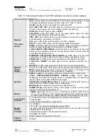
2) TRIP = finite value (TRIP mode)
In this case, the channel behaves as in the constant CURRENT mode for a time
equal to the finite value set as TRIP parameter, and then it is switched off according
to the selected
Power-Down
option (Kill/Ramp-Down). If the
Kill
option is selected,
the channel will be switched off immediately. If the
Ramp-Down
option is selected,
the voltage will drop to zero at a rate determined by the value of the
Ramp-Down
parameter programmed for that channel.
Other front panel signals and relevant LEDs are foreseen to signal the channel status,
such as OVERVOLTAGE, UNDERVOLTAGE, CHANNEL ON and TRIP. Another set of
LEDs warn about possible fault conditions in the system operation (OVER
TEMPERATURE, FAN FAILURE, POWER FAILURE). For a detailed description of
these conditions please refer to Section 4 in this manual. A description of all front panel
components can be found in the
Hardware Installation Guide
.
A RESET can be generated either manually via a front panel button or remotely by
sending a proper signal through the relevant connector. In both cases it is possible to
reset only the CPU of the system or both the CPU and the boards, depending on the
duration of the RESET signal. The System may be instructed to react to a Power On or
to a Restart bringing all the channels from zero to the programmed value without the
user's intervention via the
Power-On
parameter. If this option is enabled, the System
will recover smoothly from a power failure or RESET, automatically restoring the status
it had before the power was interrupted. KILL and INTERLOCK functions have been also
implemented and allow to drop the channel output voltage to zero, independently from
the Ramp-Down parameter set.For a detailed description of all system control and
monitoring signals and of channel parameters please refer to Section 4 in this manual.
In order to protect the System from improper use, a multilevel management of user’s
profiles has been foreseen, including the possibility of having password protection for
each channel or group of channels. In particular, three different login levels are
available:
Guest
,
User
and
Administrator
, each with different levels of access ability to
the system parameter monitoring and setting. Moreover, the possibility of defining
preferred custom environments is foreseen for each single user. Please refer to
Section 10 for further details on this subject.
Daisy-chain configuration of more SY2527 crates can be achieved by using the
H.S. CAENET connectors located on the front panel. The chain can be controlled
remotely by a SY2527 system configured as CAENET Controller allowing for
Multicrate
Operation
, i.e. the possibility of controlling and monitoring interactively the daisy-chained
crates one at a time, either from any one of the SY2527 crates of the chain or from a PC
or video terminal externally connected to any one of the crates. Moreover, in
Multicrate
Operation
it is possible to connect to the chain a SY127 system, equipped with a
A128HS board, and interact with it via H.S. CAENET. The same operation is also
possible with a SY527 system.
The Ethernet interface further extends the access facilities to the system: it allows the
use of a Browser or just a Telnet connection to monitor and control interactively each
crate connected to the network. This type of link, which can be reduced to the
Customer’s Intranet in order to have secure access, allows to perform remotely a wide
range of tasks, such as system debugging, firmware upgrading and even technical
support. A special software interface has been developed for the monitoring and setting
of system parameters from TCP/IP environment.
Further remote control interfaces are available on request and can be inserted into the
expansion slots on the front panel.


