96
EXAMPLES
STATUS VALUES IN MET ER CHANNELS
Status values are represented by 1 for on and 0 for off. This is useful when a metering channel needs to change
depending on the mode of operation. If either of two transmitters can feed the antenna and there is no power
meter after the coax switch, it would be nice to know what the power out was regardless of which transmitter is
on. Assume the following input conditions:
Status 1 is true when TX1 is ON ANT
Status 2 is true when TX2 is ON ANT
Meter 1 is TX1 Output Power
Meter 2 is TX2 Output Power
Set Meter 3 as a virtual channel with this expression:
S1 * M1 + S2 * M2
Since S1 is either 1 or 0, the first term will either be zero or the value of
meter 1. Same for S2 in the second term.
Now, whenever S1 is true, we’ll see input 1 on channel 3, and whenever S2 is
true, input 2 will be displayed. Channel 3 will always show output power
regardless of which transmitter is on.
MIN/MAX/AVERAGE
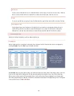
The ARC Plus Touch allows for setting metering channels to normal, minimum, maximum or average. Typically, the
real-time value is also to be displayed, so put any desired calculated values on virtual channels. In fact, you could
devote 4 channels to one input, using separate virtual channels for min, max and average. One channel would be
the actual input, say Meter 1, and the other three would be set to virtual, all with an expression of M1 but with the
sample type set differently as described in
TRANSMITTER EFFICIENCY
Transmitter efficiency is easy to calculate in real time using a virtual channel.
Here are the three actual inputs you’ll need:
Meter 1 is Input Voltage
Meter 2 is Input Current
Meter 3 is Power Out
And here is the expression for a virtual channel calculating efficiency:
M3 / M2 / M1 * 100
This assumes watts, amps and volts. (The factor of 100 converts the output into percent.) You will have to make
further adjustments for kW, KV and mA as appropriate.
We could have simply
added M1 and M2, but that
doesn’t allow for a
transmitter being operated
into a dummy load.


