


4-94
2003 Buell XB9R: Fuel System
HOME
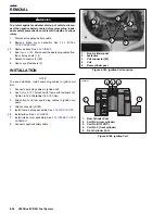
INSTALLATION
1.
See
Figure 4-179.
Coat lip of seal with a thin film of
clean
engine oil. With the lipped side facing inboard, install
new
camshaft oil seal (16) into gearcase cover (15), if
removed. Press seal into position until flush with surface
of timer bore.
2.
Install trigger rotor (17).
a. Apply LOCTITE THREADLOCKER 243 (blue) to
threads of bolt (18).
b.
Position trigger rotor (17) onto end of camshaft
aligning notch with camshaft slot.
c. Install bolt to secure rotor. Tighten to 43-53
in-lbs
(5-6 Nm).
3.
Install cam position sensor (19) and timer plate studs (4).
Rotate cam position sensor to its previously marked
position to obtain approximate ignition timing.
4.
Route sensor wiring leads and install cable straps. See
7.24 SPROCKET COVER WIRING.
5.
See
Figure 4-181.
Install sensor wiring terminals into
correct positions in plug end of connector [14]. R/W, GN/
W and BK/W wires of plug end (from cam position sen-
sor) must match same color wires in receptacle end of
connector (from ignition module wiring harness). Install
pin terminals. See
B.2 DEUTSCH ELECTRICAL CON-
NECTORS
under
B.1 AMP MULTILOCK ELECTRICAL
CONNECTORS
.
6.
See
Figure 4-179.
Attach connector [14] (6).
7.
Check ignition timing. See
1.17 IGNITION TIMING
.
8.
Tighten timer plate studs (4) to 15-30
in-lbs
(2-3 Nm).
9.
Install inner cover (20) using screws (3). Tighten to 12-20
in-lbs
(1-2 Nm).
CAUTION
Use only H-D Part No. 8699 rivets to secure outer timing
cover. These rivets are specially designed so that no
rivet end falls off into the timing compartment. Use of
regular rivets can damage ignition system components
and may allow water to enter the timing compartment.
10. Secure timer cover (2) to inner cover using
new
rivets
(1).
11. Connect negative battery cable.
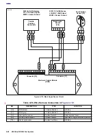
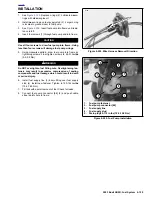
Figure 4-181. Connecting Sensor Wires
8
7
6
5
12
11
10
9
4
3
2
1
/W
GN
/W
GN
/W
BK
/W
BK
R/W
R/W
A
B
C
A
B
C
A
B
C
R/W
V/Y
BK/W
R/W
V/Y
GN/W
BK/W
b0765x7x
Throttle
Position
Sensor
[88]
Cam
Position
Sensor
[14]
ECM Connector [11]
Содержание XB9R 2003
Страница 2: ...1 2 Edit Me Printed June 5 2002 12 26 pm ...
Страница 35: ...D 2 2003 Buell XB9R Appendix D HOME Figure D 2 Rear Brake Systems Top View b1115xbx ...
Страница 36: ...2003 Buell XB9R Appendix D D 3 HOME Figure D 3 Rear Brake Systems Left Side View b1116xcx ...
Страница 44: ...2003 Buell XB9R Appendix D D 11 HOME Figure D 11 Clutch and Throttle Cables Right Side View b1124xax ...
Страница 47: ...D 14 2003 Buell XB9R Appendix D HOME NOTES ...
Страница 49: ......
Страница 77: ...1 28 2003 Buell XB9R Maintenance HOME NOTES ...
Страница 103: ...1 54 2003 Buell XB9R Maintenance HOME NOTES ...
Страница 105: ... 2 ...
Страница 191: ......
Страница 263: ...3 72 2003 Buell XB9R Engine HOME NOTES ...
Страница 299: ...4 2 2003 Buell XB9R Fuel System HOME NOTES ...
Страница 385: ...4 88 2003 Buell XB9R Fuel System HOME NOTES ...
Страница 421: ...4 124 2003 Buell XB9R Fuel System HOME NOTES ...
Страница 423: ......
Страница 445: ...5 22 2003 Buell XB9R Starter HOME NOTES ...
Страница 447: ......
Страница 469: ...6 22 2003 Buell XB9R Drive Transmission HOME NOTES ...
Страница 497: ...6 50 2003 Buell XB9R Drive Transmission HOME NOTES ...
Страница 499: ......
Страница 565: ...7 66 2003 Buell XB9R Electrical HOME NOTES ...