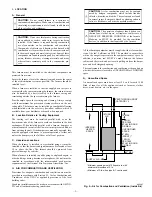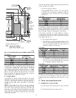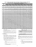
TABLE 3—OPENING DIMENSIONS (IN.)
FURNACE CASING
WIDTH
A
B
Heat-Only
Heat/Cool*
14-3/16
13-1/8
19-5/8
19-7/16
17-1/2
16-7/16
19-5/8
19-7/16
21
19-7/8
19-5/8
19-7/16
24-1/2
23-7/16
19-5/8
19-7/16
* These dimensions apply when a model CB or CD Evaporator Coil casing is
to be installed.
B.
Installation On a Combustible Floor
1. Cut and frame hole in floor per dimensions in Installation
Instructions packaged with downflow subbase.
2. When completed, downflow subbase, plenum, and furnace
(or coil casing when used) should be installed as shown in
Fig. 6.
WARNING:
DO NOT INSTALL THE FURNACE ON
ITS BACK OR SIDES; safety control operation will be
adversely affected. Never connect return-air ducts to the
sides or back of the furnace. Failure to follow this
warning could result in fire, personal injury, or death.
IV.
FILTER ARRANGEMENT
WARNING:
Never operate unit without a filter or with
filter access door removed. Failure to follow this warning
could result in fire, personal injury, or death.
The 2 factory-supplied filters are shipped in the blower compart-
ment. After the return-air duct has been connected to the furnace,
install the filters in a V-formation inside the return-air plenum.
(See Fig. 7.)
V.
GAS PIPING
Gas piping must be installed in accordance with national and local
codes. Refer to the current edition of the NFGC. Canadian
installations must be made in accordance with NSCNGPIC and all
authorities having jurisdiction.
The gas supply line should be a separate line directly from the
meter to the furnace, if possible. Refer to Table 4 for recom-
mended gas pipe sizing. Risers should be used to connect to the
furnace and to the meter.
TABLE 4—MAXIMUM CAPACITY OF PIPE*
NOMINAL
IRON
PIPE
SIZE
(IN.)
INTERNAL
DIAMETER
(IN.)
LENGTH OF PIPE (FT)
10
20
30
40
50
1/2
0.622
175
120
97
82
73
3/4
0.824
360
250
200
170
151
1
1.049
680
465
375
320
285
1-1/4
1.380
1400
950
770
660
580
1-1/2
1.610
2100
1460
1180
990
900
* Cubic ft of gas per hr for gas pressures of 0.5 psig (14-in. wc) or less, and a
pressure drop of 0.5-in. wc (based on a 0.60 specific gravity gas). Ref: Table
C-2 NFPA 54/ANSI Z223.1-1992.
Fig. 4—Floor Opening for Concrete Slab
A73382
HOLE IN
FLOOR
A
B
Fig. 5—Furnace on a Concrete Slab (Non-Garage
Installation)
A73383
FURNACE
PLENUM
Fig. 6—Furnace, Plenum, and Subbase Installed on a
Combustible Floor
A78651
DOWNFLOW
SUBBASE
SHEET METAL
PLENUM
FURNACE
(OR COIL CASING
WHEN USED)
—5—


