I.
LOCATION
A.
General
CAUTION:
Do not install furnace in a corrosive or
contaminated atmosphere. Make sure all combustion and
circulating air requirements are followed, in addition to
all local codes and ordinances.
CAUTION:
Do not use this furnace during construction
when adhesives, sealers, and/or new carpets are being
installed. If the furnace is required during construction,
use clean outside air for combustion and ventilation.
Compounds of chlorine and fluorine when burned with
combustion air form acids which will cause corrosion of
the heat exchangers and metal vent system. Some of these
compounds are found in paneling and dry wall adhesives,
paints, thinners, masonry cleaning materials, and many
other solvents commonly used in the construction pro-
cess.
This furnace must be installed so the electrical components are
protected from water.
Locate the furnace close to the chimney/vent and as near the center
of the air distribution system as possible. The furnace should be
installed level.
When a furnace is installed so that the supply ducts carry air to
areas outside the space containing the furnace, the return air must
also be handled by a duct(s) sealed to the furnace casing and
terminating outside the space containing the furnace.
Provide ample space for servicing and cleaning. Always comply
with the minimum fire protection clearances shown on the unit
rating plate. The furnace may be installed on combustible flooring
when installed with the accessory downflow subbase, which is
available from your distributor or branch when required.
B.
Location Relative to Cooling Equipment
The cooling coil must be installed parallel with or on the
downstream side of the furnace to avoid condensation in the heat
exchangers. When installed parallel with a furnace, dampers or
other means used to control the flow of air must prevent chilled air
from entering the unit. If the dampers are manually operated, they
must be equipped with means to prevent operation of either unit
unless the damper is in the full-heat or full-cool position.
C.
Hazardous Locations
When the furnace is installed in a residential garage, it must be
installed so that the burners and ignition source are located at least
18 in. above the floor. The furnace should be protected from
physical damage by vehicles.
When a furnace is installed in public garages, airplane hangars, or
other buildings having hazardous atmospheres, the unit must be
installed in accordance with the recommended good practice
requirements of the National Fire Protection Association, Inc.
II.
AIR FOR COMBUSTION AND VENTILATION
Provisions for adequate combustion and ventilation air must be
provided in accordance with Section 5.3, Air for Combustion and
Ventilation, of the NFGC or applicable provisions of the local
building codes.
Canadian installations must be made in accordance with NSCNG-
PIC and all authorities having jurisdiction.
CAUTION:
Air for combustion must not be contami-
nated by halogen compounds, which include fluoride,
chloride, bromide, and iodide. These elements are found
in aerosol sprays, detergents, bleaches, cleaning solvents,
salts, air fresheners, and other household products.
CAUTION:
The operation of exhaust fans, kitchen ven-
tilation fans, clothes dryers, or fireplaces could create a
NEGATIVE PRESSURE CONDITION at the furnace.
Make-up air MUST be provided for the ventilation
devices, in addition to that required by the furnace.
All fuel-burning equipment must be supplied with air for combus-
tion of the fuel. Sufficient air MUST be provided to ensure there
will not be a negative pressure in the equipment room or space. In
addition, a positive seal MUST be made between the furnace
cabinet and the return-air duct to avoid pulling air from the burner
area and draft safeguard opening.
The requirements for combustion and ventilation air depend upon
whether the furnace is located in a UNCONFINED or CONFINED
space.
A.
Unconfined Space
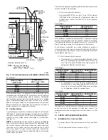
An unconfined space must have at least 50 cu ft for each 1000
Btuh of input for all the appliances (such as furnaces, clothes
dryer, water heaters, etc.) in the space.
Fig. 2—Air for Combustion and Ventilation (Inside Air)
A93387
RETURN
AIR
6
″
MIN
(FRONT)
†
SUPPLY AIR
VENT THROUGH ROOF
(CATEGORY I)
1 SQ IN.
PER 1000
BTUH* IN DOOR
OR WALL
12
″
MAX
1 SQ IN.
PER 1000
BTUH* IN DOOR
OR WALL
12
″
MAX
INTERIOR
HEATED
SPACE
* Minimum opening size is 100 square in. with
minimum dimensions of 3-In.
†
Minimum of 3-In. when type B-1 vent is used.
UNCONFINED
SPACE
—3—


