


Confidential
CHAPTER 7 SERVICE FUNCTIONS
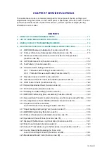
The maintenance mode is exclusively designed for the purpose of checks, settings and
adjustments using the buttons on the control panel or open/close of the front cover. You can
perform operational checks of panel PCB, sensors, perform a print test, display the log
information or error codes.
CONTENTS
2. LIST OF MAINTENANCE-MODE FUNCTIONS ...........................................................7-2
3. USER-ACCESS TO THE MAINTENANCE MODE .......................................................7-3
4. DETAILED DESCRIPTION OF MAINTENANCE-MODE FUNCTIONS........................7-4
4.1 EEPROM Parameter Initialization (Function code 01/91) .....................................7-4
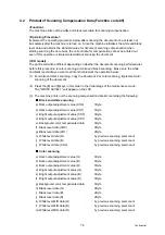
4.2 Printout of Scanning Compensation Data (Function code 05) ..............................7-5
4.3 Placement of Document Scanner Unit in Position for Transportation
4.6.1 Firmware switch setting (Function code 10).............................................7-14
4.6.2 Printout of firmware switch data (Function code 11) ................................7-18
4.8 Operational Check of Control Panel Button (Function code 13)..........................7-20
4.13 EEPROM Customizing (User-accessible) (Function code 52) ............................7-29
4.14 Received Data Transfer Function (Function code 53) (only model with FAX) .....7-30
4.15 Fine Adjustment of Scan Start/End Positions (Function code 54) .......................7-32
4.16 Acquisition of White Level Data
and CCD Scanner Area Setting (Function code 55)............................................7-34
4.19 Printout of maintenance information (Function code 77).....................................7-39
4.21 Display of the Machine’s Log Information (Function code 80).............................7-41
4.23 Output of Transmission Log to the Telephone Line (Function code 87) ..............7-43
4.24 Counter Reset After Replacing the Fuser Unit,
Laser Unit and Paper Feed Kit (Function code 88) .............................................7-44
Содержание DCP 8085DN
Страница 13: ...CHAPTER 1 SPECIFICATIONS ...
Страница 52: ...Confidential CHAPTER 2 THEORY OF OPERATION ...
Страница 69: ...2 16 Confidential 3 3 Paper Feeding Fig 2 18 LT path DX path MP path Paper tray path ...
Страница 89: ...CHAPTER 3 ERROR INDICATION AND TROUBLESHOOTING ...
Страница 178: ...Confidential CHAPTER 4 PERIODICAL MAINTENANCE ...
Страница 204: ...4 25 Confidential 23 Secure the Fuser unit with the pan B M4x20 Taptite screw Fig 4 37 Taptite pan B M4x20 Fuser unit ...
Страница 248: ...CHAPTER 5 DISASSEMBLY REASSEMBLY ...
Страница 265: ...5 12 Confidential Fig 5 7 EM2 4 places Separation pad ASSY ...
Страница 291: ...5 38 Confidential 38 Driver PCB Battery CIS model Main PCB Battery harness Drive PCB Battery Driver harness ...
Страница 400: ...5 147 Confidential 9 11 3 Printed Rubber Key 1 Remove the Printed rubber key Fig 5 170 Printed rubber key Panel cover ...
Страница 452: ...5 199 Confidential 9 33 Thermistor ASSY 1 Remove the Thermistor ASSY from the Frame L Fig 5 242 Frame L Thermistor ASSY ...
Страница 501: ...Confidential CHAPTER 6 ADJUSTMENTS AND UPDATING OF SETTINGS REQUIRED AFTER PARTS REPLACEMENT ...
Страница 507: ...6 5 Confidential 8 Alert warning message of WHQL appears Click Continue Anyway to proceed ...
Страница 516: ...CHAPTER 7 SERVICE MODE ...
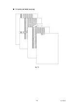
Страница 525: ...7 7 Confidential For color scanning Fig 7 2 ...
Страница 527: ...7 9 Confidential For white and black scanning Fig 7 3 ...
Страница 528: ...7 10 Confidential For color scanning Fig 7 4 ...
Страница 567: ...Confidential CHAPTER 8 CIRCUIT DIAGRAMS WIRING DIAGRAM ...
Страница 569: ...8 1 Confidential 1 CIRCUIT DIAGRAMS High voltage Power Supply PCB Circuit Diagram Fig 8 1 ...
Страница 570: ...8 2 Confidential LVPS PCB Circuit Diagram 230V Fig 8 2 ...
Страница 571: ...8 3 Confidential LVPS PCB Circuit Diagram 115V Fig 8 3 ...


