


App. 1-15
Confidential
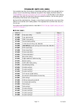
<WSW09> (Protocol definition 1)
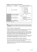
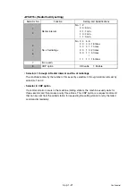
• Selector 1: Frame length selection
Usually a single frame consists of 256 octets (1 octet = 8 bits). For communications lines
with higher bit error rate, however, set selector 1 to "1" so that the machine can divide a
message into 64-octet frames.
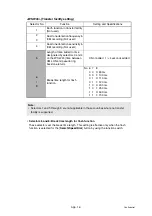
Remarks
: The error correction mode (ECM) is a facsimile transmission manner in which
the machine divides a message into frames for transmission so that if any data
error occurs on the transmission line, the machine retransmits only those
frames containing the error data.
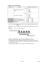
• Selector 2: Use of non-standard commands
If this selector is set to "0," the machine can use non-standard commands (the machine's
native-mode commands, e.g., NSF, NSC, and NSS) for communications. If it is set to "1,"
the machine will use standard commands only.
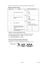
• Selectors 3 and 4: No. of retries
These selectors set the number of retries in each specified modem transmission speed.
• Selector 5: T5 timer
This selector sets the time length for the T5 timer.
• Selector 6: T1 timer
This selector sets the time length for the T1 timer.
• Selectors 7 and 8: Timeout for response from the called station in automatic sending mode
If the machine (calling station) receives no response (no G3 command) from the called
terminal in automatic sending mode for the period specified by these selectors, it
disconnects the line.
Selector No.
Function
Setting and Specifications
1
Frame length selection
0: 256 octets 1: 64 octets
2
Use of non-standard commands
0: Allowed
1: Prohibited
3
4
No. of retries
No. 3 4
0 0: 4 times
0 1: 3 times
1 0: 2 times
1 1: 1 times
5
T5 timer
0: 300 sec.
1: 60 sec.
6
T1 timer
0: 35 sec.
1: 40 sec.
7
8
Timeout for response from the
called station in automatic
sending mode
No. 7 8
0 0: 55 sec. (in U.S.A. and Canadian
models)
60 sec. (in other models)
0 1: 140 sec.
1 0: 90 sec.
1 1: 35 sec.
Note:
• Selectors 1 through 5 are not applicable in those models which do not support ECM.
Содержание DCP 8085DN
Страница 13: ...CHAPTER 1 SPECIFICATIONS ...
Страница 52: ...Confidential CHAPTER 2 THEORY OF OPERATION ...
Страница 69: ...2 16 Confidential 3 3 Paper Feeding Fig 2 18 LT path DX path MP path Paper tray path ...
Страница 89: ...CHAPTER 3 ERROR INDICATION AND TROUBLESHOOTING ...
Страница 178: ...Confidential CHAPTER 4 PERIODICAL MAINTENANCE ...
Страница 204: ...4 25 Confidential 23 Secure the Fuser unit with the pan B M4x20 Taptite screw Fig 4 37 Taptite pan B M4x20 Fuser unit ...
Страница 248: ...CHAPTER 5 DISASSEMBLY REASSEMBLY ...
Страница 265: ...5 12 Confidential Fig 5 7 EM2 4 places Separation pad ASSY ...
Страница 291: ...5 38 Confidential 38 Driver PCB Battery CIS model Main PCB Battery harness Drive PCB Battery Driver harness ...
Страница 400: ...5 147 Confidential 9 11 3 Printed Rubber Key 1 Remove the Printed rubber key Fig 5 170 Printed rubber key Panel cover ...
Страница 452: ...5 199 Confidential 9 33 Thermistor ASSY 1 Remove the Thermistor ASSY from the Frame L Fig 5 242 Frame L Thermistor ASSY ...
Страница 501: ...Confidential CHAPTER 6 ADJUSTMENTS AND UPDATING OF SETTINGS REQUIRED AFTER PARTS REPLACEMENT ...
Страница 507: ...6 5 Confidential 8 Alert warning message of WHQL appears Click Continue Anyway to proceed ...
Страница 516: ...CHAPTER 7 SERVICE MODE ...
Страница 525: ...7 7 Confidential For color scanning Fig 7 2 ...
Страница 527: ...7 9 Confidential For white and black scanning Fig 7 3 ...
Страница 528: ...7 10 Confidential For color scanning Fig 7 4 ...
Страница 567: ...Confidential CHAPTER 8 CIRCUIT DIAGRAMS WIRING DIAGRAM ...
Страница 569: ...8 1 Confidential 1 CIRCUIT DIAGRAMS High voltage Power Supply PCB Circuit Diagram Fig 8 1 ...
Страница 570: ...8 2 Confidential LVPS PCB Circuit Diagram 230V Fig 8 2 ...
Страница 571: ...8 3 Confidential LVPS PCB Circuit Diagram 115V Fig 8 3 ...


