


2-17
Confidential
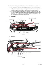
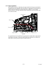
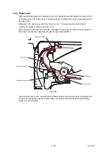
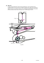
3.3.1 Plate-up Function of the Paper Tray
The plate ASSY in the paper tray is pushed up with the motor drive and not with the spring in
order to maintain the constant pressure to the feed roller and to give the paper feeding
performance.
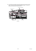
When the paper tray (Tray1 cassette) is installed to the machine, the plate is lowered.
If the main motor drives in this situation, the driving reaches the lift gear 46 through some
gears. This driving also reaches the plate up plate and it pushes up on the plate ASSY.
Fig. 2-19
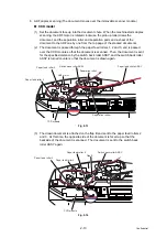
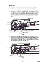
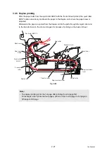
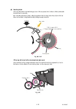
When the feed roller is pushed up, the hook is released by the lift arm, and the rotation of the
clutch gear is stopped. Then, the pressure plate is stopped to push up.
Fig. 2-20
When the tray is pulled out from the machine, the pressure plate is returned to the original
position. When the tray is put into the machine, the above operation is performed from the
start again.
Lift gear 46
Gear 21-16
Gear 15
P/P gear 22/B23
tray drive
P/P clutch hook B
Plate up plate
Plate ASSY
P/P differential
P/P gear 29 clutch cam
P/P clutch hook A2
P/P clutch hook A1
Stop
Содержание DCP 8085DN
Страница 13: ...CHAPTER 1 SPECIFICATIONS ...
Страница 52: ...Confidential CHAPTER 2 THEORY OF OPERATION ...
Страница 69: ...2 16 Confidential 3 3 Paper Feeding Fig 2 18 LT path DX path MP path Paper tray path ...
Страница 89: ...CHAPTER 3 ERROR INDICATION AND TROUBLESHOOTING ...
Страница 178: ...Confidential CHAPTER 4 PERIODICAL MAINTENANCE ...
Страница 204: ...4 25 Confidential 23 Secure the Fuser unit with the pan B M4x20 Taptite screw Fig 4 37 Taptite pan B M4x20 Fuser unit ...
Страница 248: ...CHAPTER 5 DISASSEMBLY REASSEMBLY ...
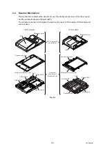
Страница 265: ...5 12 Confidential Fig 5 7 EM2 4 places Separation pad ASSY ...
Страница 291: ...5 38 Confidential 38 Driver PCB Battery CIS model Main PCB Battery harness Drive PCB Battery Driver harness ...
Страница 400: ...5 147 Confidential 9 11 3 Printed Rubber Key 1 Remove the Printed rubber key Fig 5 170 Printed rubber key Panel cover ...
Страница 452: ...5 199 Confidential 9 33 Thermistor ASSY 1 Remove the Thermistor ASSY from the Frame L Fig 5 242 Frame L Thermistor ASSY ...
Страница 501: ...Confidential CHAPTER 6 ADJUSTMENTS AND UPDATING OF SETTINGS REQUIRED AFTER PARTS REPLACEMENT ...
Страница 507: ...6 5 Confidential 8 Alert warning message of WHQL appears Click Continue Anyway to proceed ...
Страница 516: ...CHAPTER 7 SERVICE MODE ...
Страница 525: ...7 7 Confidential For color scanning Fig 7 2 ...
Страница 527: ...7 9 Confidential For white and black scanning Fig 7 3 ...
Страница 528: ...7 10 Confidential For color scanning Fig 7 4 ...
Страница 567: ...Confidential CHAPTER 8 CIRCUIT DIAGRAMS WIRING DIAGRAM ...
Страница 569: ...8 1 Confidential 1 CIRCUIT DIAGRAMS High voltage Power Supply PCB Circuit Diagram Fig 8 1 ...
Страница 570: ...8 2 Confidential LVPS PCB Circuit Diagram 230V Fig 8 2 ...
Страница 571: ...8 3 Confidential LVPS PCB Circuit Diagram 115V Fig 8 3 ...


