


3-32
Confidential
■
Error code AF
CCD model
CIS model
Document Scanner home position sensor is not turned off.
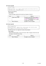
■
Error code B0
FFC for scanner module is not connected correctly or failure of the document scanner unit.
* This error is indicated on the LCD in the maintenance mode.
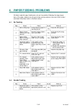
Scanner Locked
Open the Document Cover and release Scanner lock lever. Press Stop
key.
Scan Unable
See Troubleshooting and routine maintenance chapter in User's
Guide.
<User Check>
• Check that the scanner lock lever is unlocked.
- CCD model
Step
Cause
Remedy
1
Home position sensor harness not
connected correctly
Reconnect the home position sensor
harness.
2
Drive PCB failure
Replace the drive PCB.
3
Belt broken
Replace the belt.
4
Home position sensor failure
Replace the home position sensor.
5
Scanner motor failure
Replace the scanner motor.
6
Main PCB failure
Replace the main PCB ASSY.
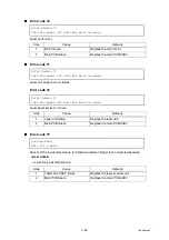
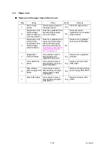
- CIS model
Step
Cause
Remedy
1
FFC cable not connected correctly
Reconnect the FFC cable.
2
Drive PCB failure
Replace the drive PCB.
3
Document scanner unit failure
Replace the document scanner unit.
4
Main PCB failure
Replace the main PCB ASSY.
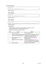
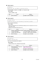
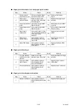
Scanner Error
Step
Cause
Remedy
1
Harness for scanner module not
connected correctly.
Reconnect the harness for the CCD unit
correctly. (CCD model)
Reconnect the harness for the document
scanner unit correctly. (CIS model)
2
Scanner harness broken
Replace the FFC cable ASSY.
3
Main PCB failure
Replace the main PCB ASSY.
Содержание DCP 8085DN
Страница 13: ...CHAPTER 1 SPECIFICATIONS ...
Страница 52: ...Confidential CHAPTER 2 THEORY OF OPERATION ...
Страница 69: ...2 16 Confidential 3 3 Paper Feeding Fig 2 18 LT path DX path MP path Paper tray path ...
Страница 89: ...CHAPTER 3 ERROR INDICATION AND TROUBLESHOOTING ...
Страница 178: ...Confidential CHAPTER 4 PERIODICAL MAINTENANCE ...
Страница 204: ...4 25 Confidential 23 Secure the Fuser unit with the pan B M4x20 Taptite screw Fig 4 37 Taptite pan B M4x20 Fuser unit ...
Страница 248: ...CHAPTER 5 DISASSEMBLY REASSEMBLY ...
Страница 265: ...5 12 Confidential Fig 5 7 EM2 4 places Separation pad ASSY ...
Страница 291: ...5 38 Confidential 38 Driver PCB Battery CIS model Main PCB Battery harness Drive PCB Battery Driver harness ...
Страница 400: ...5 147 Confidential 9 11 3 Printed Rubber Key 1 Remove the Printed rubber key Fig 5 170 Printed rubber key Panel cover ...
Страница 452: ...5 199 Confidential 9 33 Thermistor ASSY 1 Remove the Thermistor ASSY from the Frame L Fig 5 242 Frame L Thermistor ASSY ...
Страница 501: ...Confidential CHAPTER 6 ADJUSTMENTS AND UPDATING OF SETTINGS REQUIRED AFTER PARTS REPLACEMENT ...
Страница 507: ...6 5 Confidential 8 Alert warning message of WHQL appears Click Continue Anyway to proceed ...
Страница 516: ...CHAPTER 7 SERVICE MODE ...
Страница 525: ...7 7 Confidential For color scanning Fig 7 2 ...
Страница 527: ...7 9 Confidential For white and black scanning Fig 7 3 ...
Страница 528: ...7 10 Confidential For color scanning Fig 7 4 ...
Страница 567: ...Confidential CHAPTER 8 CIRCUIT DIAGRAMS WIRING DIAGRAM ...
Страница 569: ...8 1 Confidential 1 CIRCUIT DIAGRAMS High voltage Power Supply PCB Circuit Diagram Fig 8 1 ...
Страница 570: ...8 2 Confidential LVPS PCB Circuit Diagram 230V Fig 8 2 ...
Страница 571: ...8 3 Confidential LVPS PCB Circuit Diagram 115V Fig 8 3 ...


