


3-48
Confidential
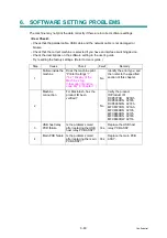
5.3
Troubleshooting for image Defect
Image defect related problems are end user recoverable if following the User Check items. If
the same problem occurs, follow each procedure in the order of the number described in the
Step column in the tables below.
■
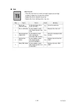
Light
<User Check>
- Check the machine's environment. Low temperature and low
humidity conditions can cause this problem.
- If the whole page is light, toner save mode may be on.
- Replace the toner cartridge or drum unit with a new one.
Step
Cause
Check
Result
Remedy
1
Dirt on exposure
drum electrode
Are the electrodes of the
drum unit and machine
body dirty?
Yes
Clean both electrodes.
2
Dirt on scanner
windows of the
laser unit
Is the scanner windows
of the laser unit dirty?
Yes
Wipe the dirt off with a soft,
clean, lint free cloth.
)
3
Toner sensor
failure
After replacing the toner
cartridge with a new
one, does the same
problem occur even
after printing several
pages?
No
Replace the toner
cartridge.
4
Does the machine start
printing even after
removing the toner
cartridge from the drum
unit?
Yes
Clean the toner sensor.
(receiving light side /
emitting light side)
Check the harness
connection of the toner
LED PCB ASSY.
(luminescence side)
Replace the toner sensor
PCB ASSY or toner LED
PCB ASSY.
5
Between the
HVPS PCB/Main
PCB connection
failure
Is the harness of the
HVPS PCB ASSY and
main PCB ASSY
connected correctly?
Yes
Reconnect the harness of
the HVPS PCB ASSY and
main PCB ASSY.
6
HVPS PCB
failure
Is the problem solved
after replacing the
HVPS PCB ASSY?
Yes
Replace the HVPS PCB
ASSY.
7
Main PCB failure Is the problem solved
after replacing the main
PCB ASSY?
Yes
Replace the main PCB
ASSY.
8
Laser unit failure
Is the problem solved
after replacing the laser
unit?
Yes
Replace the laser unit.
Содержание DCP 8085DN
Страница 13: ...CHAPTER 1 SPECIFICATIONS ...
Страница 52: ...Confidential CHAPTER 2 THEORY OF OPERATION ...
Страница 69: ...2 16 Confidential 3 3 Paper Feeding Fig 2 18 LT path DX path MP path Paper tray path ...
Страница 89: ...CHAPTER 3 ERROR INDICATION AND TROUBLESHOOTING ...
Страница 178: ...Confidential CHAPTER 4 PERIODICAL MAINTENANCE ...
Страница 204: ...4 25 Confidential 23 Secure the Fuser unit with the pan B M4x20 Taptite screw Fig 4 37 Taptite pan B M4x20 Fuser unit ...
Страница 248: ...CHAPTER 5 DISASSEMBLY REASSEMBLY ...
Страница 265: ...5 12 Confidential Fig 5 7 EM2 4 places Separation pad ASSY ...
Страница 291: ...5 38 Confidential 38 Driver PCB Battery CIS model Main PCB Battery harness Drive PCB Battery Driver harness ...
Страница 400: ...5 147 Confidential 9 11 3 Printed Rubber Key 1 Remove the Printed rubber key Fig 5 170 Printed rubber key Panel cover ...
Страница 452: ...5 199 Confidential 9 33 Thermistor ASSY 1 Remove the Thermistor ASSY from the Frame L Fig 5 242 Frame L Thermistor ASSY ...
Страница 501: ...Confidential CHAPTER 6 ADJUSTMENTS AND UPDATING OF SETTINGS REQUIRED AFTER PARTS REPLACEMENT ...
Страница 507: ...6 5 Confidential 8 Alert warning message of WHQL appears Click Continue Anyway to proceed ...
Страница 516: ...CHAPTER 7 SERVICE MODE ...
Страница 525: ...7 7 Confidential For color scanning Fig 7 2 ...
Страница 527: ...7 9 Confidential For white and black scanning Fig 7 3 ...
Страница 528: ...7 10 Confidential For color scanning Fig 7 4 ...
Страница 567: ...Confidential CHAPTER 8 CIRCUIT DIAGRAMS WIRING DIAGRAM ...
Страница 569: ...8 1 Confidential 1 CIRCUIT DIAGRAMS High voltage Power Supply PCB Circuit Diagram Fig 8 1 ...
Страница 570: ...8 2 Confidential LVPS PCB Circuit Diagram 230V Fig 8 2 ...
Страница 571: ...8 3 Confidential LVPS PCB Circuit Diagram 115V Fig 8 3 ...


