


3-9
Confidential
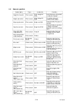
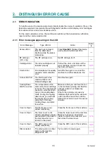
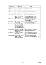
3. ERROR CODES
This machine includes a self-diagnosis function. If the machine does not work normally it
judges that an error has occurred, and indicates the corresponding error message on the
LCD, which in turn helps the end user to quickly find out the problem.
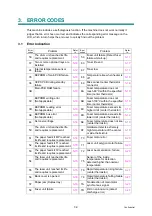
3.1
Error Indication
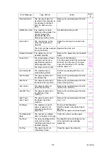
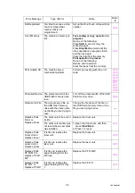
Error
codes
Problem
Refer
to:
Error
codes
Problem
Refer
to:
1E The drum unit reached its life
and requires replacement.
59 Fuser unit failure (Detect fuser
failure at start-up)
1F Two or more optional trays are
installed
63 Toner life end
24 Internal temperature sensor
failure
67 Toner low
35 EEPROM of main PCB failure
68 Temperature rise when heater is
off
36 HVPS PCB during standby
failure
69 Mis-connect center thermistor
connector
3B
Main PCB RAM failure
6A
Fuser temperature does not
reach 60°C within the specified
time (center thermistor)
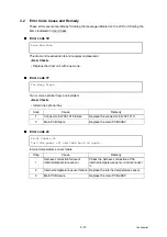
3C
EEPROM writing error
(Not applicable)
6B
Fuser temperature does not
reach 100°C within the specified
time (center thermistor)
3D EEPROM reading error
(Not applicable)
6C Fuser temperature exceeds its
higher limit (center thermistor)
3E EEPROM bus error
(Not applicable)
6D Fuser temperature exceeds its
lower limit (center thermistor)
44 No toner cartridge
6E Fuser temperature does not rise
(center thermistor)
50
The drum unit reached its life
and requires replacement.
6F
Hardware detects extremely
high temperature of the center
or side thermistors
51 The paper feed kit MP reached
its life and requires replacement.
70 Fuser motor error
52 The paper feed kit T1 reached
its life and requires replacement.
71 Laser unit polygon motor failure
53 The paper feed kit T2 reached
its life and requires replacement.
72 Laser beam emission failure
54
The fuser unit reached its life
and requires replacement.
75
Sensor of the inside
temperature for detection
detected higher than normal
temperature
55 The laser unit reached its life
and requires replacement.
76 Rapid temperature rising failure
(center thermistor)
56 Back cover is opened
78 Rapid temperature falling failure
(center thermistor)
57 Paper jam (Duplex tray)
7A No detection of main motor
synchronous signal
58 Fuser unit failure
7D Dirt on corona wire (detect
discharge error)
Содержание DCP 8085DN
Страница 13: ...CHAPTER 1 SPECIFICATIONS ...
Страница 52: ...Confidential CHAPTER 2 THEORY OF OPERATION ...
Страница 69: ...2 16 Confidential 3 3 Paper Feeding Fig 2 18 LT path DX path MP path Paper tray path ...
Страница 89: ...CHAPTER 3 ERROR INDICATION AND TROUBLESHOOTING ...
Страница 178: ...Confidential CHAPTER 4 PERIODICAL MAINTENANCE ...
Страница 204: ...4 25 Confidential 23 Secure the Fuser unit with the pan B M4x20 Taptite screw Fig 4 37 Taptite pan B M4x20 Fuser unit ...
Страница 248: ...CHAPTER 5 DISASSEMBLY REASSEMBLY ...
Страница 265: ...5 12 Confidential Fig 5 7 EM2 4 places Separation pad ASSY ...
Страница 291: ...5 38 Confidential 38 Driver PCB Battery CIS model Main PCB Battery harness Drive PCB Battery Driver harness ...
Страница 400: ...5 147 Confidential 9 11 3 Printed Rubber Key 1 Remove the Printed rubber key Fig 5 170 Printed rubber key Panel cover ...
Страница 452: ...5 199 Confidential 9 33 Thermistor ASSY 1 Remove the Thermistor ASSY from the Frame L Fig 5 242 Frame L Thermistor ASSY ...
Страница 501: ...Confidential CHAPTER 6 ADJUSTMENTS AND UPDATING OF SETTINGS REQUIRED AFTER PARTS REPLACEMENT ...
Страница 507: ...6 5 Confidential 8 Alert warning message of WHQL appears Click Continue Anyway to proceed ...
Страница 516: ...CHAPTER 7 SERVICE MODE ...
Страница 525: ...7 7 Confidential For color scanning Fig 7 2 ...
Страница 527: ...7 9 Confidential For white and black scanning Fig 7 3 ...
Страница 528: ...7 10 Confidential For color scanning Fig 7 4 ...
Страница 567: ...Confidential CHAPTER 8 CIRCUIT DIAGRAMS WIRING DIAGRAM ...
Страница 569: ...8 1 Confidential 1 CIRCUIT DIAGRAMS High voltage Power Supply PCB Circuit Diagram Fig 8 1 ...
Страница 570: ...8 2 Confidential LVPS PCB Circuit Diagram 230V Fig 8 2 ...
Страница 571: ...8 3 Confidential LVPS PCB Circuit Diagram 115V Fig 8 3 ...


