


7-4
Confidential
4. DETAILED DESCRIPTION OF
MAINTENANCE-MODE FUNCTIONS
4.1
EEPROM Parameter Initialization (Function code 01/91)
<Function>
The machine initializes the parameters, user switches, and firmware switches registered in
the EEPROM, to the initial values. Entering the function code 01 initializes all of the
EEPROM areas, but entering 91 does not initialize some areas, as listed below.
<Operating Procedure>
(1) Press the [
0
] and [
1
] keys (or the [
9
] and [
1
] keys according to your need) in this order in
the initial stage of the maintenance mode.
The "PARAMETER INIT" will appear on the LCD.
(2) Upon completion of parameter initialization, the machine returns to the initial stage of the
maintenance mode.
(3) Press the [
9
] key twice to exit from the maintenance mode.
(4) Turn the machine power off.
Note:
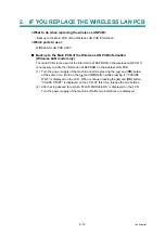
• If you replace the main PCB with the one used for any other machine, customize the
EEPROM (maintenance mode function code 74 in
) and then carry out
this procedure.
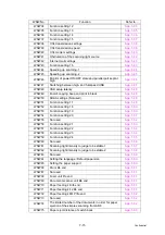
Function code
Data item
01
91
Maintenance-mode functions
User switches
Firmware switches
Remote activation code
Station ID data
Outside line number
Telephone function registration
One-touch dialing
Speed dialing
Group dialing
All of these will
beinitialized.
These will be
initialized.
These will not
be initialized.
These will not
be initialized.
Содержание DCP 8085DN
Страница 13: ...CHAPTER 1 SPECIFICATIONS ...
Страница 52: ...Confidential CHAPTER 2 THEORY OF OPERATION ...
Страница 69: ...2 16 Confidential 3 3 Paper Feeding Fig 2 18 LT path DX path MP path Paper tray path ...
Страница 89: ...CHAPTER 3 ERROR INDICATION AND TROUBLESHOOTING ...
Страница 178: ...Confidential CHAPTER 4 PERIODICAL MAINTENANCE ...
Страница 204: ...4 25 Confidential 23 Secure the Fuser unit with the pan B M4x20 Taptite screw Fig 4 37 Taptite pan B M4x20 Fuser unit ...
Страница 248: ...CHAPTER 5 DISASSEMBLY REASSEMBLY ...
Страница 265: ...5 12 Confidential Fig 5 7 EM2 4 places Separation pad ASSY ...
Страница 291: ...5 38 Confidential 38 Driver PCB Battery CIS model Main PCB Battery harness Drive PCB Battery Driver harness ...
Страница 400: ...5 147 Confidential 9 11 3 Printed Rubber Key 1 Remove the Printed rubber key Fig 5 170 Printed rubber key Panel cover ...
Страница 452: ...5 199 Confidential 9 33 Thermistor ASSY 1 Remove the Thermistor ASSY from the Frame L Fig 5 242 Frame L Thermistor ASSY ...
Страница 501: ...Confidential CHAPTER 6 ADJUSTMENTS AND UPDATING OF SETTINGS REQUIRED AFTER PARTS REPLACEMENT ...
Страница 507: ...6 5 Confidential 8 Alert warning message of WHQL appears Click Continue Anyway to proceed ...
Страница 516: ...CHAPTER 7 SERVICE MODE ...
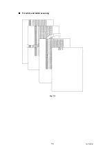
Страница 525: ...7 7 Confidential For color scanning Fig 7 2 ...
Страница 527: ...7 9 Confidential For white and black scanning Fig 7 3 ...
Страница 528: ...7 10 Confidential For color scanning Fig 7 4 ...
Страница 567: ...Confidential CHAPTER 8 CIRCUIT DIAGRAMS WIRING DIAGRAM ...
Страница 569: ...8 1 Confidential 1 CIRCUIT DIAGRAMS High voltage Power Supply PCB Circuit Diagram Fig 8 1 ...
Страница 570: ...8 2 Confidential LVPS PCB Circuit Diagram 230V Fig 8 2 ...
Страница 571: ...8 3 Confidential LVPS PCB Circuit Diagram 115V Fig 8 3 ...


