


7-11
Confidential
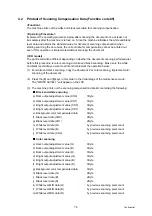
4.3
Placement of Document Scanner Unit in Position for Transportation
(Function code 06)
<Function>
This function is to move the document scanner unit in position for transportation located at
the left end.
When you fix the FAX equipment and check its operation, you need to perform this function
right before packing and shipping it.
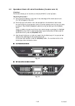
<Operating Procedure>
(CCD model)
(1) Press the [
0
] and [
6
] keys in this order in the initial stage of the maintenance mode.
The CCD unit moves to the designated position for transportation located at the left end.
The "MAINTENANCE 06" is displayed until the CCD unit is placed in position.
When the CCD unit is placed in the position, the "PLEASE SCAN LOCK" appears on the
LCD.
(2) Open the document cover, and lock the scanner lock lever at the rear left of the
document scanner unit. When the scanner lock lever is locked, the "SCAN LOCKED"
appears.
To terminate this operation, press the [
Stop/Exit
] button. The machine returns to the
initial stage of the maintenance mode. The machine will be unable to scan after this
operation until switch OFF/ON is pressed or the "Function 99" is performed.
(CIS model)
(1) Press the [
0
] and [
6
] keys in this order in the initial stage of the maintenance mode.
The "SCAN LOCKED" appears on the LCD, when the CIS moves in position for
transportation located.
Note:
• Please instruct end users to perform this function if possible before packing and
shipping their FAX equipment to a sales agent or a service dealer for the purpose of
repair. (For the procedure to allow users to perform maintenance modes, please
see
Содержание DCP 8085DN
Страница 13: ...CHAPTER 1 SPECIFICATIONS ...
Страница 52: ...Confidential CHAPTER 2 THEORY OF OPERATION ...
Страница 69: ...2 16 Confidential 3 3 Paper Feeding Fig 2 18 LT path DX path MP path Paper tray path ...
Страница 89: ...CHAPTER 3 ERROR INDICATION AND TROUBLESHOOTING ...
Страница 178: ...Confidential CHAPTER 4 PERIODICAL MAINTENANCE ...
Страница 204: ...4 25 Confidential 23 Secure the Fuser unit with the pan B M4x20 Taptite screw Fig 4 37 Taptite pan B M4x20 Fuser unit ...
Страница 248: ...CHAPTER 5 DISASSEMBLY REASSEMBLY ...
Страница 265: ...5 12 Confidential Fig 5 7 EM2 4 places Separation pad ASSY ...
Страница 291: ...5 38 Confidential 38 Driver PCB Battery CIS model Main PCB Battery harness Drive PCB Battery Driver harness ...
Страница 400: ...5 147 Confidential 9 11 3 Printed Rubber Key 1 Remove the Printed rubber key Fig 5 170 Printed rubber key Panel cover ...
Страница 452: ...5 199 Confidential 9 33 Thermistor ASSY 1 Remove the Thermistor ASSY from the Frame L Fig 5 242 Frame L Thermistor ASSY ...
Страница 501: ...Confidential CHAPTER 6 ADJUSTMENTS AND UPDATING OF SETTINGS REQUIRED AFTER PARTS REPLACEMENT ...
Страница 507: ...6 5 Confidential 8 Alert warning message of WHQL appears Click Continue Anyway to proceed ...
Страница 516: ...CHAPTER 7 SERVICE MODE ...
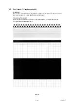
Страница 525: ...7 7 Confidential For color scanning Fig 7 2 ...
Страница 527: ...7 9 Confidential For white and black scanning Fig 7 3 ...
Страница 528: ...7 10 Confidential For color scanning Fig 7 4 ...
Страница 567: ...Confidential CHAPTER 8 CIRCUIT DIAGRAMS WIRING DIAGRAM ...
Страница 569: ...8 1 Confidential 1 CIRCUIT DIAGRAMS High voltage Power Supply PCB Circuit Diagram Fig 8 1 ...
Страница 570: ...8 2 Confidential LVPS PCB Circuit Diagram 230V Fig 8 2 ...
Страница 571: ...8 3 Confidential LVPS PCB Circuit Diagram 115V Fig 8 3 ...


