27
The connection of the thermo-stove must be done with rigid aluminized steel pipes or stainless steel pipes.
It is
forbidden the use of flexible metallic pipes or fibre cement pipes because they damage the safety of the
connection because they are subject to jerks and breaks, which causes smoke looses.
Materials that are prohibited for the chimney and, therefore, damage the proper functioning of the equipment
are: fibre cement, galvanized steel and rough and porous interior surfaces. A example of solution is described
below:
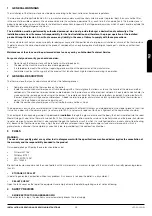
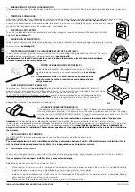
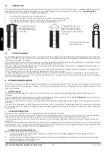
(1) Stainless steel AISI 316 chimney with double insulated chamber and material resistant up to 400°C.
Efficiency 100% optimum (
see drawing D8
).
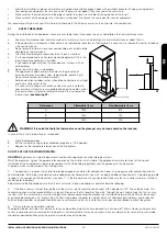
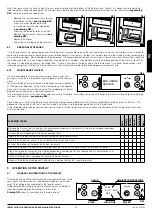
All thermo-stoves that send smoke to the
exterior should have their own chimney. Never use the same chimney for
several equipments at the same time (
see drawing D9
).
It is not recommended the fit in horizontals sections. The horizontal section
will not be longer than 3 meters.
It must be installed a “T” with hermetic cover at the thermo-stove exit
smoke that allows the regular inspection or the heavy dust download.
There will not be more than 4 changes of direction, including the register
“T” for the cleaning.
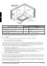
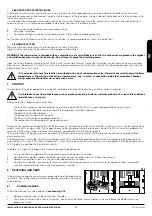
In
drawing D10
are represented the basic requirements for the chimney
installation of a thermo-stove:
The flue must be away from flammable or combustible materials through
an appropriate insulation or an air chamber. Inside the pipes, it is
forbidden the use of air abduction channels. It is also prohibited to do
mobile or fixed openings for connecting other different equipments.
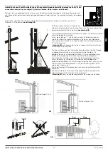
The smoke duct must be staunchness set to the equipment and it can
have a maximum inclination of 45° whereby excessive deposits of
condensation produced in the initial stages of ignition and / or excessive
soot formation is avoided. Moreover, it avoids the slowing down of the
smoke when it comes out.
The lack of sealing of the connection may cause the malfunction of the
equipment.
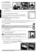
The internal diameter of the connection pipe should correspond to the
external diameter of the chimney of the equipment.
In
drawing D11
you can see the requirements for a correct installation.
D8
Minimum height 1.5 m
Minimum height 1.5 m
D10
D11
D9
EN
INSTALLATION, OPERATING AND SERVICING INSTRUCTIONS
HYDRO SERIES
Содержание Dama Hydro
Страница 107: ...106 12 1 DAMA H FT ...
Страница 109: ...108 12 2 LETICIA H FT ...
Страница 111: ...110 12 3 REYNA H FT ...

