28
5.3
CHIMNEY COWL
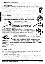
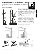
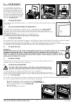
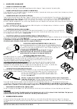
The chimney draught also depends on the chimney cowl. Therefore, in case of an artisanal chimney cowl, it is indispensable the exit section
would be twice the inside section of the smoke duct. The smoke throughout will be assured even in presence or air (
see drawing D12
).
The chimney cowl must comply with the following requirements:
•
It must have the same interior section of the chimney.
•
It must have an usable exit section that is two times the one of the interior of the chimney.
•
It must be constructed so that the rain, snow or any other objet do not enter inside.
•
It must be easily accessible in order to do servicing and cleaning tasks.
5.4
OUTSIDE AIR INTAKE
For the proper operation of the thermo-stove, it is essential that there is enough air for the combustion and re/oxygenation of the environment
where it is installed. This means that the air must be able to move for the combustion through some openings connected to the exterior, even
when doors and windows are closed.
It must be placed in so that it cannot be obstructed. It must be connected to the environment where the equipment is installed and it must be
protected by a grate. The minimum area of the outlet should not be less than 100 cm2.
When the air flow comes through openings that are connected to the exterior of adjacent environments, it is important to avoid air intakes in
connection with garages, kitchens, toilets, etc.
The boiler or thermo-stove is provided with a necessary air intake for the combustion on the back side (40 mm diameter). It is important this
intake is not blocked and to respect the recommended distances to the wall or near items.
It is recommended the primary air intake connection of the thermo-stove with the outside although it is not obligatory. The connection tube
material can be made in any material (PVC, aluminium, polyethylene, etc.), not necessarily metallic. Consider that inside this duct is going to
pass air at the outside temperature.
6
HYDRAULIC INSTALLATION
The Bronpi “hydro” series has been designed for installation with a closed expansion tank, where the water contained does not communicate
direct or indirectly with the atmosphere. In general, the installation of closed expansion tank is provided with a pre-charged closed vessel with
a gas-tight membrane.
•
SAFETY VALVES
The thermo-stove is provided with a safety valve set at 3 bars pressure, in order to work during possible increases of pressure on the
installation.
The discharge flow rate of the safety valve must allow to discharge an amount of vapour not lower than
Q / 0.58 [kg. h]
, where Q is the useful
power transferred to the water of the generator expressed in kilowatts.
The fitter must control the maximum pressure in each point of the installation so that it does not pass the maximum working pressure of each
component.
The safety valve is placed on the top of the boiler or thermo-stove, next to the exit tube. The discharge tube of the safety valve must be made
so that it allows the normal operation and does not cause damages to people; the discharge must end near to the safety valve and be visible
and accessible.
•
CLOSED EXPANSION TANK
The thermo-stove is provided with a 6 l. closed expansion tank, pre-charged at 1.5 bars.
The maximum working pressure of the vessel is lower than the calibrated pressure of the safety valve. The fitter must anticipate the capacity
of the expansion vessel by analysing the total capacity of the installation and placing another additional vessel if necessary.
The closed expansion vessels must conform to the provisions in terms of design, fabrication, conformity assessment and use for pressure
equipments.
In case of multiple heating generators (boilers that use other fuels or wood-burning thermo-fireplaces) that work in the same installation or the
same secondary circuit, it is compulsory to connect each generator with an expansion vessel, completely scaled for the total volume of water
contained in the same installation and in the same independent circuit.
•
CONTROLS AT THE FIRST START-UP
Before the connection of the thermo-stove make:
a.
A careful cleaning of all installation pipes to remove any residues that may damage the operation of some components of the
installation (pumps, valves, etc.)
b.
A control to check the correct draught of the smoke exit, the absence of strangulations and make sure that there are not discharges
from other equipments in the smoke exit duct.
c.
The correct purged of the installation.
D12
(1) Industrial chimney of
prefabricated elements
that allow a good smoke
extraction.
(2) Traditional chimney. The
proper exit section must be,
at least, two times the interior
section of the chimney. The best
is 2.5 times.
(3) Chimney with interior cone
smoke baffle-plate.
INSTALLATION, OPERATING AND SERVICING INSTRUCTIONS
HYDRO SERIES
EN
Содержание Dama Hydro
Страница 107: ...106 12 1 DAMA H FT ...
Страница 109: ...108 12 2 LETICIA H FT ...
Страница 111: ...110 12 3 REYNA H FT ...

