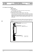
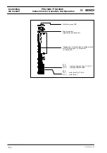


PSU 5000 / PSG 3000
Installation
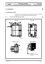
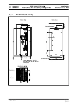
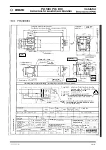
Dimensions of PSG
Instructions for Assembly and Operation
1070 078 224--109
10--6
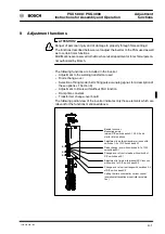
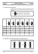
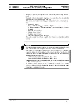
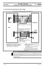
10.2.3
PSG 3100.00 A
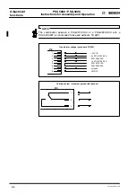
!
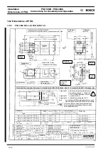
All sides 4 x M8 -- 10 deep
All sides 2 x
∅
6
H7
-- 8 deep
View X:
Connection M: white, brown: Current transformer, second-
ary measuring voltage U
m
= 150 mV / kA
2.5 % at ohmic resistance of 1kOhm
Connection T1: 1 x rectifier set 80
û
C
Connection T2: 2 x transformer primary side 150
û
C
Earth
For removing the MPE neutral earth conductor, a
suitable protective measure to EN 50063 is to be
installed.
In this case, the earth connection between the trans-
former neutral and the earthing bolt must be crossed out
in an indelible manner.
Terminal connector
external
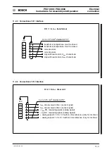
Type:
Primary
voltage
Frequency
Prim.
perman.
current max.
Short---circuit values
Voltage
Power factor
Current
Part no.
No---load
direct voltage
Level U1
Level U2
Level U4
Level U3
Level U5
Continuous
forward current
Continuous forward
current power
Max. rated surge
forward current
max. direct current
(see diagram)
(duty cycle, n periods)
Dimensions without tolerances are subject
to ”mean” deviations to DIN 7168
Standards:
Diode type
Degree of protection
Transformer
Primary terminal area
Prot. as delivered
Transformer
insulation class
Mass
Colour
yellow
Substitute
for drawing
dated
Drawn
Checked
Date
Name
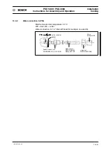
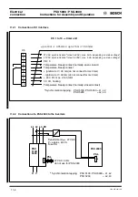
MF Transformer---Rectifier Unit
Cooling water
inlet G 1/4”
Cooling water
outlet G 1/4”
Thermal release
Rectifier
Contact surfaces
Connection T
Thermal release
Connection lines
150 mm long (T+M)
Cooling water quantity:
Max. pressure drop:
Standard:
Te
chn.
alt
er
at
ions
re
se
rv
ed
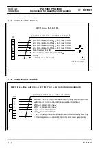
Touch guard required for primary connection!
For connection, cover type and order data, cf. attached sheet no. SKT 0058
with
100% duty cyc.
100% duty cyc.
Connection M
Current transformer
M 8 (8x)
15 deep
Nameplates
M 5 (4x)
10 deep
M 5 (4x)
15 deep
Diode type
M 8 (3x)
10 deep
Accessories (supplied loosely): 4 straight pins ISO 8735 diam. 06x12; 3 contact pins MC180 diam. 08
Earthing sign
Information sign
Содержание PSG 3000 Series
Страница 1: ...PSU 5000 PSG 3000 Instructions for Assembly and Operation MF Welding Inverters 109 Version ...
Страница 3: ......
Страница 5: ...PSU 5000 PSG 3000 Instructions for Assembly and Operation 1070 078 224 109 ...
Страница 57: ...PSU 5000 PSG 3000 Monitoring and diagnostics Instructions for Assembly and Operation 1070 078 224 108 7 6 ...
Страница 79: ...PSU 5000 PSG 3000 Installation Cooling Instructions for Assembly and Operation 1070 078 224 108 10 12 ...
Страница 97: ...PSU 5000 PSG 3000 Connection Instructions for Assembly and Operation 1070 078 224 109 11 18 ...
Страница 101: ...PSU 5000 PSG 3000 Maintenance Instructions for Assembly and Operation 1070 078 224 108 13 2 ...
Страница 105: ...PSU 5000 PSG 3000 Instructions for Assembly and Operation Accessories 1070 078 224 108 14 4 ...
Страница 107: ...PSU 5000 PSG 3000 Instructions for Assembly and Operation Storage and transport 1070 078 224 108 15 2 ...
Страница 109: ...PSU 5000 PSG 3000 Instructions for Assembly and Operation Declaration of conformity 1070 078 224 108 16 2 ...
Страница 113: ...PSU 5000 PSG 3000 Instructions for Assembly and Operation Index 1070 078 224 109 17 4 ...
Страница 114: ...1070 078 224 109 98 10 GB MBA AT VWS Printed in Germany ...


