


PSU 5000 / PSG 3000
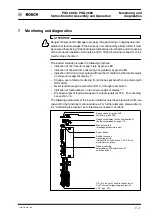
Monitoring and
diagnostics
Instructions for Assembly and Operation
1070 078 224--- 108
7---2
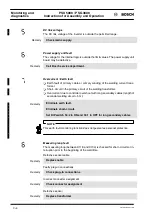
7.1 ”Inverter ready” LED
The LED is lighted when
-- no inverter fault message is active
-- the ”Stop current” input signal is not active. The function of ”Stop current” cor-
responds to an
inverted
”external enable” signal.
0V at X21/pin 6:
output stage is switched on
+24V at X21/pin 6:
output stage is blocked.
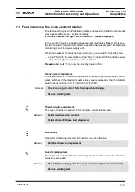
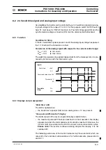
7.2 ”Weld time” LED
The LED is lighted when
-- 5 kHz firing pulses arrive from the timer (at X5, pins 6 and 7), or
-- the ”weld time” input signal (at X22, see Section 8) is high
7.3 ”Max. pulse width reached” display
The decimal point of the seven--segment display is lighted when
-- the maximum pulse width is reached. In control operation, this display appears
only when the commanded current cannot be reached. In this case, the inverter
must have worked at the limit for at least 5 consecutive mains cycles.
Please note:
The inverter continues working despite this display. It is not switched
off!
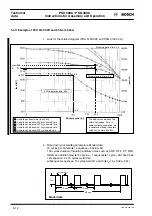
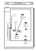
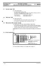
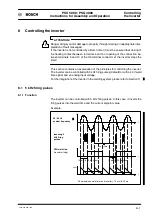
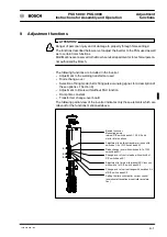
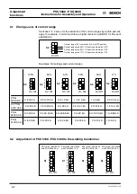
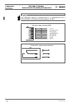
7.4 X21 pin assignment
ext. reset
Voltage supply for signal outputs
(24V, max. 2A)
Signal outputs for
fault code (e.g. for
evaluation by a
PLC)
+24V
X21
1
2
3
4
5
6
7
8
0 V
Stop Current
(+24V: output stage blocked)
all inputs: 24 VDC, 20 mA
all outputs: 24 VDC, max. 100 mA
up to 10 m: 0.75 mm
2
up to 75 m: 1.5 mm
2
O1
O3
O2
O4
For the encoding of outputs A1 to A4, please refer to page 7--5.
Содержание PSG 3000 Series
Страница 1: ...PSU 5000 PSG 3000 Instructions for Assembly and Operation MF Welding Inverters 109 Version ...
Страница 3: ......
Страница 5: ...PSU 5000 PSG 3000 Instructions for Assembly and Operation 1070 078 224 109 ...
Страница 57: ...PSU 5000 PSG 3000 Monitoring and diagnostics Instructions for Assembly and Operation 1070 078 224 108 7 6 ...
Страница 79: ...PSU 5000 PSG 3000 Installation Cooling Instructions for Assembly and Operation 1070 078 224 108 10 12 ...
Страница 97: ...PSU 5000 PSG 3000 Connection Instructions for Assembly and Operation 1070 078 224 109 11 18 ...
Страница 101: ...PSU 5000 PSG 3000 Maintenance Instructions for Assembly and Operation 1070 078 224 108 13 2 ...
Страница 105: ...PSU 5000 PSG 3000 Instructions for Assembly and Operation Accessories 1070 078 224 108 14 4 ...
Страница 107: ...PSU 5000 PSG 3000 Instructions for Assembly and Operation Storage and transport 1070 078 224 108 15 2 ...
Страница 109: ...PSU 5000 PSG 3000 Instructions for Assembly and Operation Declaration of conformity 1070 078 224 108 16 2 ...
Страница 113: ...PSU 5000 PSG 3000 Instructions for Assembly and Operation Index 1070 078 224 109 17 4 ...
Страница 114: ...1070 078 224 109 98 10 GB MBA AT VWS Printed in Germany ...


