


PSU 5000 / PSG 3000
Technical
data
Instructions for Assembly and Operation
1070 078 224--108
5--4
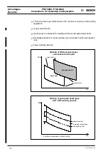
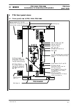
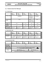
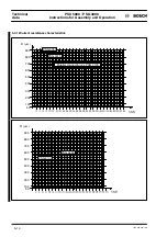
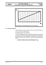
5.3 Load diagrams
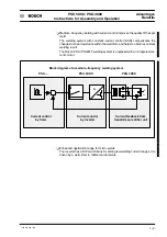
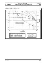
5.3.1 Performance features of PSU 5100.XXX
The PSU 5100.XXX inverter has been adapted to the capacity of the transformer--
rectifier units type PSG 3050.XXX, PSG 3075.XXX and PSG 3100.XXX. In com-
bination with a transformer--rectifier type PSG 3100.XXX, its peak current is
approx. 18 kA (with ~ 9% duty cycle)
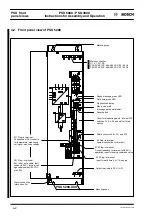
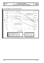
5.3.2 Performance features of PSU 5300.XXX
The PSU 5300.XXX inverter (mechanically identical with PSU 5100.XXX) supplies
peak currents up to 36 kA (with ~ 1 to 2% duty cycle) when combined with a trans-
former--rectifier type PSG 3100.XXX. With a PSG 3050.XXX or PSG 3075.XXX,
the amount of current is limited by the transformer.
Thus, the inverter type PSU 5300.XXX lies between PSU 5100.XXX and PSU
5200.XXX in the secondary range.
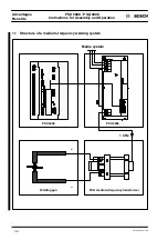
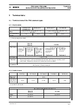
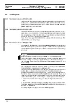
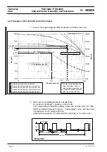
5.3.3 Performance features of PSU 5200.XXX
In combination with
two
PSG 3100.XXX
connected in parallel
, the inverter type
PSU 5200.XXX supplies a peak current up to 54 kA. When used in conjunction with
a PSG 3200.XXX, peak currents up to 40 kA can be attained. The no--load voltage
is 14 Volts.
NOTE
Danger of damage to property through inadmissibly high welding current!
You should therefore check the load diagrams in order to determine whether the
maximum welding current of your application is within the admissible ranges.
The modules should only be operated with appropriate cooling (cf. also
Section 10.3)!
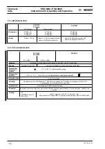
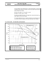
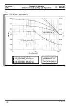
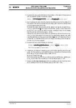
The load diagrams define the maximum admissible welding current of the PSU/
PSG combinations depending on the duty cycle (ED).
The maximum admissible welding current depends not only on the duty cycle of the
rectifier diodes, but also on the duty cycle of the PSG (transformer) used.
All diagrams are based on the thermal transient recovery times (integration time) of
the rectifier diodes (2 seconds) and the transformers (60 seconds). These fixed
values and some application--related values (number of spot welds per minute,
number of weld time cycles, number of cycles duration) are used to determine
1. the maximum admissible welding current depending on the diode load
and
2. the maximum admissible welding current depending on the transformer load.
For proper execution of the welding task the lowermost of these two values
must not be exceeded!
An example is given on page 5--12 and the following pages.
Содержание PSG 3000 Series
Страница 1: ...PSU 5000 PSG 3000 Instructions for Assembly and Operation MF Welding Inverters 109 Version ...
Страница 3: ......
Страница 5: ...PSU 5000 PSG 3000 Instructions for Assembly and Operation 1070 078 224 109 ...
Страница 57: ...PSU 5000 PSG 3000 Monitoring and diagnostics Instructions for Assembly and Operation 1070 078 224 108 7 6 ...
Страница 79: ...PSU 5000 PSG 3000 Installation Cooling Instructions for Assembly and Operation 1070 078 224 108 10 12 ...
Страница 97: ...PSU 5000 PSG 3000 Connection Instructions for Assembly and Operation 1070 078 224 109 11 18 ...
Страница 101: ...PSU 5000 PSG 3000 Maintenance Instructions for Assembly and Operation 1070 078 224 108 13 2 ...
Страница 105: ...PSU 5000 PSG 3000 Instructions for Assembly and Operation Accessories 1070 078 224 108 14 4 ...
Страница 107: ...PSU 5000 PSG 3000 Instructions for Assembly and Operation Storage and transport 1070 078 224 108 15 2 ...
Страница 109: ...PSU 5000 PSG 3000 Instructions for Assembly and Operation Declaration of conformity 1070 078 224 108 16 2 ...
Страница 113: ...PSU 5000 PSG 3000 Instructions for Assembly and Operation Index 1070 078 224 109 17 4 ...
Страница 114: ...1070 078 224 109 98 10 GB MBA AT VWS Printed in Germany ...


