background image

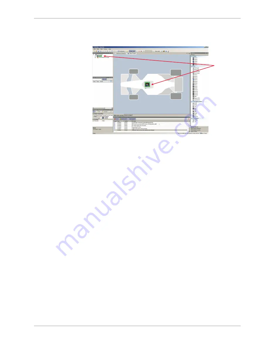
After the reset RaceCon reconnects to the DDU 8. Local configuration on both
the PC and DDU 8 match (Indicated by green background and dot). The DDU 8 is
now connected to RaceCon.


Green back-
ground and 
dot indicate 
matching 
configuration 

Feature activation

▪ Optional software feature packages are available for the DDU 8.
▪ If you have purchased an optional software feature package, it must be acti‐

vated before it becomes operational.

▪ The feature activation status is stored permanently in the device and requires

activating once only.

▪ As the activation key is device specific, a key delivered with one DDU 8 does

not work on any other DDU 8.

▪ If you have not purchased an option package, the next steps can be skipped.


7.2

Starting up | 7


Bosch Motorsport

DDU 8 Manual

23 / 160

Содержание DDU 8

Страница 1: ...Display DDU 8 Manual V1 2 9 16 2016 ...

Страница 2: ...ration 34 8 1 Display page setup 34 8 2 Display element configuration 35 8 3 LEDs 43 8 4 Page select 47 8 5 Display and LED brightness 49 8 6 Math and condition channels 49 8 7 Condition channels 53 8 8 CPU Load Limits 56 9 CAN Bus 58 9 1 CAN bus trivia 58 9 2 CAN input 59 9 3 CAN output 65 10 Analog and Frequency Inputs 71 10 1 Features 71 10 2 Analog inputs 71 10 3 Configuring inputs 72 10 4 Com...

Страница 3: ...eacon 130 14 2 Counting outing laps fragments 134 14 3 Lap timing 135 14 4 Segment timing 138 14 5 Countdown timer 140 15 Firmware 141 15 1 Firmware and configuration 141 15 2 Firmware update 141 16 Clone the Unit 144 17 GPS Sensor 146 17 1 GPS Global Positioning System 146 17 2 Protocol 146 17 3 Sensor recommendation 146 17 4 Measurement labels 147 17 5 GPS troubleshooting 148 18 Fuel Consumption...

Страница 4: ...Read the manual carefully and follow the application hints step by step Don t hesitate to contact us contact data can be found on the last page of this docu ment Disclaimer Due to continuous enhancements we reserve the rights to change any illustra tions photos and technical data within this manual Please retain this manual for your records In this document all screenshots are created by way of ex...

Страница 5: ... to the negative battery terminal Connection should be free from dirt grease paint anodizing etc Use large diameter wire More metal to metal contact is better The following notations for power signals are used KL 15 is a switched battery rail controlled by the IGN switch KL 30 is an unswitched battery positive rail same as battery positive terminal KL 31 is an unswitched ground rail same as batter...

Страница 6: ...Onboard Network Concept 3 3 Onboard Network Concept 6 160 DDU 8 Manual Bosch Motorsport ...

Страница 7: ...m the DDU 8 is sold as display only Software upgrades for the DDU 8 field upgradable by entering a key activate data logger functionality ad ditional recording on USB flash drive CCP master and additional input channels Application Display 5 graphic colour display Multiple user configurable display pages 10 multi colour RGB gearshift lights Resolution 800 x 480 high resolution pixel Supported imag...

Страница 8: ... loads 14 W at 14 V Inputs Page brightness selection 2 Analog channels 4 Input range 0 to 5 V Resolution 12 bit Switchable pull up resistor 3 kΩ Outputs PWM outputs low side switch 2 A 4 Sensor supply 5 V 1 350 mA 1 Software Configuration via RaceCon over Ethernet or MSA Box II Environment External switch for page selection 12 steps B 261 209 658 01 External switch for brightness adjust ment or pa...

Страница 9: ...ugged USB flash drive 2 GB Bosch File System BFS for mat included works with Bosch File System BFS preformatted USB Flash drive only Adapter cable to USB Port included F 02U V01 343 01 Adapter for wiring harness included F 02U 002 996 01 Connectors and Wires Motorsport connectors double density 2 x 41 pins Mating connector red AS DD 6 12 41SN F 02U 002 216 01 Mating connector yellow AS DD 6 12 41S...

Страница 10: ...nd leave the REVn_M pin open Page selection switch Pin 36 of the DDU 8 life connector is used as a page selection switch for the dis play The internal pull up resistor is automatically activated Display pages are se lected by connecting the pin to SENSGND with different resistor values over a 12 position switch Page Resistor Value Page 1 43 9 Ohm Page 2 142 Ohm Page 3 264 Ohm Page 4 409 Ohm Page 5...

Страница 11: ...rrent Maximum PWM switch frequency is 8 kHz with a 0 to 100 duty cycle Each output is short circuit protected to GND and battery voltage It is mandatory to connect the LS_PWM pins to vehicle GND as indicated in the circuit diagram when using the PWM outputs Sensor power supply The DDU 8 has 3 types of sensor power supply 12 V unregulated battery voltage 5 V and 10 V regulated voltage The 12 V unre...

Страница 12: ...Name Description Used for DDU 8 Pin 1 Terminal 30 Permanent positive Pin 2 Terminal 15 Switched positive Pin 3 Terminal 31 GND Pin 4 CAN High Diagnostic CAN bus Pin 16 CAN Low Diagnostic CAN bus Pin 10 K Line ECU diagnosis Pin 8 Ethernet RxD Ethernet interface Pin 9 Ethernet RxD Ethernet interface Pin 11 Ethernet TxD Ethernet interface Pin 12 Ethernet TxD Ethernet interface Pin 22 Screen Cable scr...

Страница 13: ...s Bidirectional dataline 23 24 25 26 USB_Power USB_DP USB_DM USB_GND USB power USB data USB data USB ground Input input input input 27 SENSPWR5_1 5 V power supply for an alog sensors output 28 SENSGND_1 sensor ground 1 output 29 TimeSync signal of synchronisation input used for timing of system compo nents 30 LS_GND_1 PWM ground output 31 LS_SWITCH_1 PWM lowside switch 1 input 32 LS_SWITCH_2 PWM l...

Страница 14: ... 8 9 RS232_1_TX RS232_1_RX RS232_1 transmit data RS232_1 receive data Bidirec tional da taline used for telemetry link 10 11 RS232_2_TX RS232_2_RX RS232_2 transmit data RS232_2 receive data Bidirec tional da taline used for GPS sen sor 12 RS232_GND RS232 ground 13 14 REV1_P REV1_M speed signal 1 positive ind and hall speed signal 1 negative ind input 15 16 REV2_P REV2_M speed signal 2 positive ind...

Страница 15: ...16 analog signal 16 input 31 ANA17 analog signal 17 input 32 ANA18 analog signal 18 input 33 ANA19 analog signal 19 input 34 ANA20 analog signal 20 input 35 ANA21 analog signal 21 input 36 ANA22 analog signal 22 input 37 ANA23 analog signal 23 input 38 ANA24 analog signal 24 input 39 ANA25 analog signal 25 input 40 ANA26 analog signal 26 input 41 LAP_TRIG laptrigger input input Inputs and Outputs ...

Страница 16: ...Mechanical Drawing 6 6 Mechanical Drawing 16 160 DDU 8 Manual Bosch Motorsport ...

Страница 17: ... 1 2 3 12 V supply voltage Pin 4 5 GND supply voltage Pin 6 Ethernet Tx Pin 7 Ethernet Tx Pin 8 Ethernet Rx Pin 9 Ethernet Rx Pin 10 Ethernet Screen Setting up the network interface The DDU 8 contains a DHCP server network addresses can be assigned automat ically to the configuration PC The IP address of DDU 8 is 10 10 0 207 1 Switch off the PC s firewall 2 Set up the PC s network interface as sho...

Страница 18: ...torsport hardware products It is used to set up configure and calibrate the DDU 8 For better understanding Bosch Motorsport offers a video tutorial that explains many functions of RaceCon The video tutorial is available in the Software Down load section of www bosch motorsport com Connecting the Unit to RaceCon The following screenshot shows an overview of the RaceCon Main Screen with its areas 7 ...

Страница 19: ...All sub windows are resizable and dockable 1 Start the RaceCon software Starting up 7 Bosch Motorsport DDU 8 Manual 19 160 ...

Страница 20: ...elect the DDU 8 and drag it into the Main Area A pop up window to specify the DDU 8 program archive appears An information shows that the archive is valid or not Select the program archive delivered with the DDU 8 PST file 7 Starting up 20 160 DDU 8 Manual Bosch Motorsport ...

Страница 21: ...rdware configura tion 7 Click Finish The DDU 8 is inserted into the project and RaceCon tries to connect to the device RaceCon detects configuration differences between the DDU 8 and the Race Con project and asks for permission for data download Starting up 7 Bosch Motorsport DDU 8 Manual 21 160 ...

Страница 22: ...8 Click OK to proceed Successful Ethernet connection DDU talks to PC The download starts and the DDU 8 carries out a reset 7 Starting up 22 160 DDU 8 Manual Bosch Motorsport ...

Страница 23: ...ackages are available for the DDU 8 If you have purchased an optional software feature package it must be acti vated before it becomes operational The feature activation status is stored permanently in the device and requires activating once only As the activation key is device specific a key delivered with one DDU 8 does not work on any other DDU 8 If you have not purchased an option package the ...

Страница 24: ...in Area 1 st Double click on DDU 8 2 nd Click on Features Info The DDU 8 features info window appears Locked disabled Unlocked activated Feature status List of features available 2 Double click on the feature you want to activate A feature unlock window appears 7 Starting up 24 160 DDU 8 Manual Bosch Motorsport ...

Страница 25: ...cle the power of DDU 8 First display configuration Quick start This chapter explains the configuration of a display element showing the battery voltage See chapter Display element configuration 35 for a detailed instruction to configure display elements 1 Expand the DDU 8 Project Tree by clicking 2 Double click on New Page The DDU 8 display configuration area opens Click Double click New Page 7 3 ...

Страница 26: ...ox shows that it is not linked to a measure ment channel 4 In the DDU 8 Project Tree click on DDU 8 to display the available measure ment channels 5 In the data window scroll down to ub measurement channel for battery voltage Scroll down to ub Click DDU 8 7 Starting up 26 160 DDU 8 Manual Bosch Motorsport ...

Страница 27: ...t channel from the Data Area and drop it on the Large Element 7 Right click on DDU 8 in the DDU 8 Project Tree and choose Download Con figuration Click Download configuration Starting up 7 Bosch Motorsport DDU 8 Manual 27 160 ...

Страница 28: ...d Telemetry for a detailed instruction to con figure recordings This function requires the installation of Software Upgrade 1 For data recording on the DDU 8 the software upgrade DDU 8 Datalogger must be activated See chapter Feature activation 23 for an instruction to activate software up grades on DDU 8 1 Expand the DDU 8 Project Tree by clicking 2 Expand the Logger Tree by clicking 3 Double cli...

Страница 29: ...DDU 8 Project Tree click on DDU 8 to display the available measurement channels In the data window scroll down to ub measurement channel for battery voltage Click DDU 8 Scroll down to ub 6 Drag drop the ub measurement channel into the recording area Drag Drop Starting up 7 Bosch Motorsport DDU 8 Manual 29 160 ...

Страница 30: ...iguration The configuration download starts and the DDU 8 carries out a reset As we did not define global start conditions recording starts immediately 8 Start the WinDarab software 9 Disconnect the DDU 8 network cable 10 Click on the Import Export icon 7 Starting up 30 160 DDU 8 Manual Bosch Motorsport ...

Страница 31: ...asurement Data dialog opens 12 Click on Modify button and select the base folder 13 Choose FTP as data transmission method 14 Choose XXXXXXXXXXX in the Vehicle dropdown list 15 Activate Auto save 16 Click Save when done Choose DDU8 in Dropdown List Starting up 7 Bosch Motorsport DDU 8 Manual 31 160 ...

Страница 32: ... Open measurement file 20 Select the measurement files from the storage folder 21 Click on Open 22 Click in New Desktop to open a new measurement data window 23 Drag the ub measurement channel from the Channel list and drop it into the measurement data window ub measurement channel s graph is displayed Notice For more detailed descriptions and instructions refer to the WinDarab V7 manual 7 Startin...

Страница 33: ...ator Once this accumulator is charged correctly by 12 V supply of the DDU 8 Date Time can be programmed by RaceCon We recommend min 5 hours charge time Please connect the DDU 8 to the PC and click on Set Date Time in the Context menu of the DDU 8 7 5 Starting up 7 Bosch Motorsport DDU 8 Manual 33 160 ...

Страница 34: ...ges All Pages Display elements placed on this page are displayed on all pages Recommended for Alarm display elements Single Page Display elements placed on this page are displayed only on this page The priority of display elements placed on All Pages is higher than the priority of display elements placed on single pages Example An Alarm placed on All Pages is displayed on all display pages and is ...

Страница 35: ... pages Display element configuration Numeric display element Adding a numeric display element to display page The Large Element and the Medium Element numeric display elements differ in element and font size The element and font size can be changed using the Nu meric Wizard Notice In this view the displayed values are random values and do not show the real values of the measurement channels 8 1 3 ...

Страница 36: ...ric element box shows that it is not linked to a measurement channel Drag Drop 2 Drag a measurement channel from the Data Area and drop it on the numeric display element The measurement channel is linked to the numeric display element Drag Drop 8 Display Configuration 36 160 DDU 8 Manual Bosch Motorsport ...

Страница 37: ...s e Enter the number of decimal places of the measurement channel f Choose the font size alignment borderstyle background and foreground color of the numeric display element g Click the Extended button to show further options to change the color of the title border and text individually 2 Click OK when done Bargraph display element Bargraph display element Drag the Bargraph display element from th...

Страница 38: ... the physical value where the Bargraph ends e Choose the background color of the Bargraph f Choose the foreground color of the Bargraph g Click the Extended button to show further options to change the color of the title border and text individually 2 Click OK when done Notice The tab Conditional Formatting is explained in chapter Condi tional formatting 42 Alarm display element The Alarm display ...

Страница 39: ...asurement channel e Choose the type of input data Value Gear Time in different formats f Enter the number of decimal places of the measurement channel g Choose the font size alignment borderstyle background and foreground color of the Alarm display element 2 Switch to the tab Alarm representation a Choose if the alarm can be reset or not b Choose if the alarm blinks slowly fast or does not blink c...

Страница 40: ...ion is TRUE i e result of the calculation is 0 c Enable the checkbox if you want to define parts of the image as transparent d Select the basic transparent color key This means that any pixel of the image near depending of the tolerance value to this color gets transparent e Select a tolerance in percent to define parts of the image as transparent 2 Switch to the tab Alarm representation It is con...

Страница 41: ...lements are available Label A label displaying a specified text Picture element An element displaying a static picture e g temperature warning Adding a Label or picture display element to display page Drag the Label or picture display element from the Toolbox and drop it on the display page Configuring a Label display element 1 Double click on the Label display element The Label Wizard window open...

Страница 42: ...r the limit value when the formatting is active c Enter the limit value when the reset hysteresis function is active The reset hysteresis function avoids the high frequent switchover of the measurement channel value d Choose the borderstyle background and foreground color of the numeric display element e Click the Extended button to show further options to change the color of the title border and ...

Страница 43: ...border and text individually If a Bargraph display element is used its colors can also be changed 3 Click OK when done Context menu The context menu appears by right clicking on a display element Change type of display element Move element to different page Remove assigned measurement channel Delete element Manage overlapping elements Insert element into library in toolbox Copy element to differen...

Страница 44: ... gear 2 50 ASCII quantization is standard for the gear channel of Bosch ECUs If you get the gear information of a different control unit as the Bosch ECU e g a gearbox control unit use the Gear Lookup Table to translate numeric values to ASCII format For more information see chapter Converting a gear channel to ASCII representation g Choose the number and color of the LEDs corresponding to the RPM...

Страница 45: ...pears Gear Lookup Table Wizard 1 Set up the settings as shown in the screenshot 2 Click OK when done The Create channel on DDU 8 window appears Enter the name and an optional description of the translated ASCII measure ment channel 3 Click Ok when done Display Configuration 8 Bosch Motorsport DDU 8 Manual 45 160 ...

Страница 46: ... d Check the box to show a demo of the LEDs Important to check blinking To create a LED that alternately blinks in two different colors choose Display on pattern and define the LEDs in the one color Then choose Display off pattern and define the LEDs in the other color 2 Click OK when done 3 The configuration is displayed in the DDU 8 LED Configuration window Assigning display pattern priority Ass...

Страница 47: ...A01 3 kOhm pull up resistor in DDU 8 automatically activated 12 position switch connects resistor to GND 43 9 142 264 409 609 846 1 180 1 650 2 430 3 830 6 980 23 200 Ohm Display pages selectable by page select switch 8 4 8 4 1 Display Configuration 8 Bosch Motorsport DDU 8 Manual 47 160 ...

Страница 48: ...tor in DDU 8 automatically activated Application page control from steering wheel or motorcycle Display page selected at power down will show up at next power up automati cally The software calibration variable DISPLAY_SWITCH needs to be set 0 Rotary switch 1 Up Down switch 2 Up Down switch with wrap around By default the DDU 8 is configured for a 12 position rotary switch Connection diagram of up...

Страница 49: ...ess switch Click on the Settings tab to display brightness controls Setting for LED brightness of maximum Setting for display brightness of maximum Connection diagram of brightness switch Write configuration to DDU 8 to activate changed brightness settings Math and condition channels Math channels Math channel Arithmetic and logical operations on up to 4 measurement channel s Numerical result 8 5 ...

Страница 50: ...isplay elements numeric ele ments alarms Bargraphs and further calculations in the whole RaceCon project All math channels can be used globally in the whole DDU 8 project Creating a new math channel 1 Follow the steps shown in the screenshot 1 st Double click on Math Channels in DDU 8 Project Tree 2 nd Click on Add channel The create edit math channel window appears Create Edit Math Channel Window...

Страница 51: ... math channel is displayed in the DDU 8 math channel window Creating a new conditional function 1 Follow the steps shown in the screenshot 2nd Click on the dropdown arrow beside Add channel 3rd Choose Conditional Function 1st Double click on Math Channels in Project Tree The create edit conditional function window appears Create Edit Conditional Function Window 1 Define the conditional function us...

Страница 52: ...on entered in the IF window is TRUE the program calculates the condition entered in the THEN window The returned value is the content of the new variable entered in Name If the condition entered in the IF window is FALSE the program calculates the condition entered in the OTHERWISE window The returned value is the content of the new variable entered in Name The reset value is always set for the ne...

Страница 53: ... is caused by the THEN condition because p_br_front_mx 30 is still bigger than p_br_front 25 As p_br_front rises to 40 As p_br_front 40 is bigger than p_br_front_mx 30 the new value for p_br_front_mx is set to 40 As p_br_front falls below 20 the IF condition turns to FALSE Now the OTH ERWISE condition is triggered Because the condition p_br_front_mx sets the value of p_br_front_mx and the value th...

Страница 54: ...ject Creating a new condition channel 1 Follow the steps shown in the screenshot 1st Double click on Conditional Channels in Project Tree 2nd Click on Add condition The create edit condition window appears Create Edit Condition Window 1 Define the condition channel using the following configuration possibilities 8 7 1 8 Display Configuration 54 160 DDU 8 Manual Bosch Motorsport ...

Страница 55: ...or condition the operator and enter the value of up to 5 constants d Enter the minimal time to detect the signal of the measurement channel to avoid high frequent switchovers e Enter the time the signal of the measurement channel is delayed after its ending f Choose the output setting of the result Constant TRUE FALSE Result is as a constant with the value TRUE or FALSE Blinking Result is a blinki...

Страница 56: ...inking Result is a blinking if the condition is fulfilled Pulse Result is a short one time pulse if the condition is fulfilled Toggling output Result is a pulse that lasts until the next condition is fulfil led 3 Click Finish when done The conditional combination is displayed in the DDU 8 condition channel win dow CPU Load Limits As all microprocessors the DDU 8 s processor has limited capacities ...

Страница 57: ...5 CPU load the DDU 8 creates an error memo ry entry To trigger this error entry the CPU load must exceed the limit for 5 mi nutes without interruption When being confronted with this error memory entry see Error info in RaceCon or when being confronted with DDU 8 resets due to complex configuration set ups please consider reducing the demands on the DDU 8 adapting the influenc ing factors mentione...

Страница 58: ...her CAN bus trivia CAN message 11 Bit standard or 29 Bit extended identifier Up to 8 bytes of data payload CAN bus Needs termination resistors 120 Ohm in wiring harness All devices connected to the bus must use identical data rate Configuration of DDU 8 bus data rate by double click on the CAN bus in project tree 1 MBaud 500 kBit 250 kBit 125 kBit Row counter concept Re use multiplex of message id...

Страница 59: ...put of desired bus CAN1 or CAN2 2 Select New CAN Channel from menu 3 Insert name and description of channel 4 Click OK when done The channel is listed in the Data window and a CAN channel configuration win dow opens 9 2 9 2 1 9 2 2 CAN Bus 9 Bosch Motorsport DDU 8 Manual 59 160 ...

Страница 60: ... ID Check the box if extended IDs 29 bit are used c If replacement values are used specify time out period and raw value d Check the box if a multiplexer row counter is used e Enter data position length and format f The bargraph shows assignment of the bytes Red colored fields show the assignment of the data bytes Orange colored fields show the assignment of the multiplexer bytes Representation Bi...

Страница 61: ... Select unit of physical value e Enter minimum physical limit of the channel for manual setup f Enter maximum physical limit of the channel for manual setup g Check the box to automatically adjust the limits of the channel Special features CAN analyzer functionality This functionality is only available if a MSA Box I II is used to connect the DDU 8 to the PC Choose the CAN bus that is connected to...

Страница 62: ...ject Tree Measurement Sheet 1 is displayed in Main Area 2 Click on Measurement elements in the Toolbox 3 Drag the desired Measurement element e g Numeric Indicator and drop it on the Measurement Sheet Drag Drop 4 Click on folder CAN Input of desired CAN bus to display available channels 5 Drag desired Measurement channel and drop it on the Measurement ele ment 9 2 7 9 CAN Bus 62 160 DDU 8 Manual B...

Страница 63: ...t DBC file from menu A file browser opens 3 Select DBC file to import and click OK when done A channel import window opens 4 Select desired channels on the left and use the Add button to add them to import list 5 Click OK when complete The channels are inserted in the Data window Export RaceCon CAN configuration 1 Right click on CAN Input of desired bus CAN1 or CAN2 2 Select Export from menu An Ex...

Страница 64: ...ens 3 Select the input file and click OK An Import Selection window opens Drag Drop 4 Select channels to import 5 Drag and drop the channel to CAN Input of desired CAN bus on right hand side 6 Click Next If a measurement channel belongs to more than one source e g C 60 and ECU MS 5 1 the Solve Label Ambiguity window opens 9 2 10 9 CAN Bus 64 160 DDU 8 Manual Bosch Motorsport ...

Страница 65: ...e format It will open an explorer window where the dbc file can be saved on the harddisc CAN output Output configuration Create new CAN output message channel 1 Right click on CAN Output of desired bus CAN1 or CAN2 2 Select New CAN Message from menu The Create new CAN message window opens 9 2 11 9 3 9 3 1 9 3 2 CAN Bus 9 Bosch Motorsport DDU 8 Manual 65 160 ...

Страница 66: ... counter multiplexer 5 Click OK when done A CAN message configuration window opens in the Main Area 6 Click on DDU 8 in the DDU 8 Project Tree to display all labels 7 Select the desired measurement channel and drop it on message s bytes 9 CAN Bus 66 160 DDU 8 Manual Bosch Motorsport ...

Страница 67: ...owing dia logue In this dialogue additional settings are possible Representation Also a Bitwise CAN signal can be defined Please define posi tion and length in this case Quantization Physical values can be calculated by entering Factor Offset Signed and unsigned is optional CAN Bus 9 Bosch Motorsport DDU 8 Manual 67 160 ...

Страница 68: ...gth Define start position and length of multiplexer Byte or Bitwise possible Endianness Define Byte order Little Endian LB HB Big Endian HB LB Export RaceCon CAN configuration 1 Right click on CAN Output of desired bus CAN1 or CAN2 2 Select Export from menu The Export Selection window opens 3 Specify the filename 9 3 3 9 3 4 9 CAN Bus 68 160 DDU 8 Manual Bosch Motorsport ...

Страница 69: ...Select the input file and click OK An Import Selection window opens 4 Select channels to import 5 Drag and drop the channel to CAN Output of desired CAN bus on right hand side 6 Click Next If a measurement channel belongs to more than one source e g C 60 and ECU MS 5 1 the Solve Label Ambiguity window opens 9 3 5 CAN Bus 9 Bosch Motorsport DDU 8 Manual 69 160 ...

Страница 70: ...7 Assign the ambiguous channels to the desired source 8 Click Finish 9 CAN Bus 70 160 DDU 8 Manual Bosch Motorsport ...

Страница 71: ...ectable Analog inputs Measurement channels For each analog channel several subchannels are available Measurement labels with the characters raw show the exact values in mV Measurement labels with the characters _fi show filtered values The word name in the table is a placeholder for the channel s name Measurement label Function raw_name mV value of sensor raw_name_fi filtered mV value of sensor na...

Страница 72: ...Expand the list of I O Channels by clicking on in the DDU 8 Project Tree 3 Drag the Bosch Sensor Wizard from the Toolbox and drop it on the desired analog input channel in the DDU 8 Project Tree The Bosch Sensor Wizard opens 3rd Select the exact type Opens sensor s datasheet 2nd Narrow your choice by choosing a type These calibration values will be used 1st Choose the sensor s category 4 Click Fin...

Страница 73: ...sor raw_name_fi filtered mV value of sensor name physical value of sensor name_fi filtered physical value Configuring a generic linear sensor Example Acceleration sensor 5 g From sensor data sheet operating characteristics Sensitivity 400 mV g Offset 2500 mV The sensor has a linear output signal with sensitivity and offset 1 Click on Measurement Sources in the Toolbox 2 Expand the list of I O Chan...

Страница 74: ...U 8 It allows you to use a push button The fixed value of the internal pullup resistor is 3010 Ohm If using an addi tional external pullup resistor set up the overall resistance 5 Click Next when done The second part of the Sensitivity Offset Wizard opens Choose unit group and unit of physical value Enter values from sensor datasheet Electrical pin value Physical channel value 6 Click Next when do...

Страница 75: ...eactivated Sensitivity and Offset value for sensor Adjustment is enabled Channel is linked to ANA04 Available measurements for channel Measurement label Function raw_name mV value of sensor raw_name_fi filtered mV value of sensor name physical value of sensor name_fi filtered physical value Configuring a generic non linear sensor Example Thermistor 5 kOhm From sensor data sheet resistance values o...

Страница 76: ...it on the desired analogue input channel in the DDU 8 Project Tree A Characteristic Curve Wizard opens 4 To activate the internal pull up resistor check the box The DDU 8 pull up resistor is used to get a 5V signal at the analogue channel of the DDU 8 It allows you to use a push button The fixed value of the internal pull up resistor is 3010 Ohm If using an addi tional external pull up resistor se...

Страница 77: ... not need offset calibration Physical limits of channel Enter name to automatically create a new measurement sheet Notice Working with automatically created measurement sheets is ex plained in chapter Setting up an online measurement 92 7 Click Finish when done 8 Enter channel name and description 9 Click OK when done The channel is inserted into the DDU 8 Project Tree Input pin Pull up resistor i...

Страница 78: ...nt Sources in the Toolbox 2 Expand the list of I O Channels by clicking on in the DDU 8 Project Tree 3 Drag the Multipoint Adjustment analog signal source from the Toolbox and drop it on the desired analog input channel in the DDU 8 Project Tree 4 A Multipoint Adjustment Wizard opens 5 To activate the internal pullup resistor check the box The internal pullup resistor is used to get a 5 V signal a...

Страница 79: ...nable additonal online calibration Physical limits of channel Enter name to automatically create a new measurement sheet Notice Working with automatically created measurement sheet is ex plained in chapter Setting up an online measurement 92 8 Click Finish when done 9 Enter channel name and description 10 Click OK when done The channel is inserted into the DDU 8 Project Tree Analog and Frequency I...

Страница 80: ...filtered mV value of sensor name physical value of sensor name_fi filtered physical value Online definition of the curve is covered in the chapter Online calibration of measurement channels 97 of this manual Digital filter details DDU 8 uses A D converter oversampling and digital filtering to recording rate Digital filters eliminate out of band noise 10 3 5 10 Analog and Frequency Inputs 80 160 DD...

Страница 81: ...rded data Filtering is smart averaging over several samples Filtered signal is delayed with respect to real time signal DDU 8 filters have constant frequency independent delay Delay e g 22 samples at 10 ms is corrected during recording No delay filtered vs unfiltered in recorded data Correction is of course not possible for real time data display online PWM out Use filtered data for recording use ...

Страница 82: ... Correvit Set to 0 for wheelspeed measurement Number of teeth on the pulse wheel Enter name to automatically create a new measurement sheet 5 Click Finish when done 6 Enter channel name and description 7 Click OK when done The channel is inserted into the DDU 8 Project Tree Input pin has hall interface Number of teeth Wheel circumference Channel is linked to REV01 Available measurements for channe...

Страница 83: ... in a special section Example Sensitivity offset calculation on input channel 1 Click Measurement Sources in the Toolbox 2 Drag the Sensitivity Offset computed source from the Toolbox and drop it on Computed Channels in the DDU 8 Project Tree A Computed Sensitivity Offset Wizard opens Choose unit group and unit of output Enter sensitivity and offset of conversion formula Choose input channel 3 Cli...

Страница 84: ...lick Finish when done 6 Enter channel name and description 7 Click OK when done The channel is inserted into the DDU 8 Project Tree Hysteresis The hysteresis function avoids the high frequent switchover of the measurement channel value The hysteresis can be adjusted for each input measurement chan nel individually and can be used for further processing 1 Click Measurement Sources in the Toolbox 2 ...

Страница 85: ...ime when the hysteresis function is activated after vehicle s startup j Enter the channel s state A or B at startup 4 Click Next when done The second part of the Hysteresis Wizard opens Check the box to force the channel s quantization if the quantization should be a fixed value in the whole CAN system Choose data type of the measurement variable Enter name to automatically create a new measuremen...

Страница 86: ... as input Calculated speed is average of both speeds if speed difference between wheels limit Calculated speed is maximum of both speeds if speed difference between wheels limit Calculating vehicle speed of 4 wheel drive Wheel speeds of all wheels as in put Calculated speed is speed of 2nd fastest wheel Setting up calculated speed 1 Click on tab System Overview 2 Click on Measurement Sources in th...

Страница 87: ...tion Choose device 4 Click Finish when done The speed calculation is inserted into the DDU 8 Project Tree Configu ration window Measurement channels calculated speed and calculated distance Speed calculation in DDU 8 Project Tree Configuring PWM outputs PWM Pulse Width Modulation Output frequency is constant 10 6 Analog and Frequency Inputs 10 Bosch Motorsport DDU 8 Manual 87 160 ...

Страница 88: ... Time Output frequency Duty cycle 20 switch closed Output frequency Time Uout Duty cycle 80 Configuring a PWM output 1 Click on Measurement Sources in the Toolbox 2 Drag the PWM Out computed source from the Toolbox and drop it on the desired PWM_OUT channel in the DDU 8 Project Tree 3 A PWM Out Wizard opens 10 6 1 10 Analog and Frequency Inputs 88 160 DDU 8 Manual Bosch Motorsport ...

Страница 89: ...nfiltered values for this purpose Notice The power on state of the PWM output is switch open 0 duty cycle 4 Click Finish when done 5 Enter channel name and description 6 Click OK when done The channel is inserted into the DDU 8 Project Tree Characteristic curve Output frequency Channel is linked to PWM_OUT02 Measurement channels Measurement label Function pwm_err_ls_out_01_OL PWM output 1 error op...

Страница 90: ...el Function pwm_err_ls_out_01_SCG PWM output 1 error short circuit to GND Tab 1 Diagnostic channels Notice The diagnosis of PWM output 2 4 is similar 10 Analog and Frequency Inputs 90 160 DDU 8 Manual Bosch Motorsport ...

Страница 91: ...ommunication interface Ethernet Communication protocol XCP Achieving an online connection Set up the PC for access to the Unit 1 Switch off local firewall on the PC 2 Set IP Configuration for the Ethernet interface to automatic configuration DHCP See chapter Setting up the network interface 17 for details 3 Start RaceCon 4 Establish the Ethernet connection to the vehicle 5 Power on the vehicle Sta...

Страница 92: ...on download is necessary Configuration download 1 Right click on DDU 8 in the DDU 8 Project Tree 2 Select Download configuration The configuration download starts A Green dot and background indicate a successful download Setting up an online measurement DDU 8 supports online measurement of sensor values and diagnostic variables Expand Measurement Container and Measurement Folder 1 in the Project T...

Страница 93: ...e the folder can be renamed and deleted It also allows the creation of measurement pages From the context menu of a measurement page the page can be renamed and deleted To change between different pages click on the tabs on the bottom of the Main Project Area Online Measurement 11 Bosch Motorsport DDU 8 Manual 93 160 ...

Страница 94: ...on DDU 8 in the Project Tree to display all measurement channels 3 Select the desired measurement channel and drop it on the measurement el ement If the DDU 8 is online the value is displayed Drag Drop The measurement element s appearance can be changed using the Properties Menu RaceCon offers different types of measurement elements 11 Online Measurement 94 160 DDU 8 Manual Bosch Motorsport ...

Страница 95: ...asurement sheets with the DDU 8 as well as with all other devices connected to RaceCon 1 During the configuration of a measurement channel select a measurement sheet from the list box or enter a name for a new measurement sheet Select existing sheet from list or enter name of new sheet 2 To create the sheets right click on DDU 8 and select Create measurement views from the DDU 8 context menu 11 2 ...

Страница 96: ...nction zeros only when this functionality is activated in the settings of this channel see chapter Enable online offset calibration for measurement channel 97 Using the measurement sheets 1 When RaceCon is online press the F11 key to switch from Design Mode in to Race Mode The measurement sheet is extended to full screen The but ton for offset calibration is active 2 Switch between different sheet...

Страница 97: ... online offset calibration Example acceleration sensor Enable online offset calibration for measurement channel During creation of the measurement channel Check box to enable online offset calibration and enter desired physical target value In the channel view 11 3 11 3 1 Online Measurement 11 Bosch Motorsport DDU 8 Manual 97 160 ...

Страница 98: ...offset is now calibrated Group adjustment Group adjustment is the simultaneous online calibration of several channels This is useful e g to set all wheel forces and damper positions to 0 when the vehicle is positioned on a flat patch Configuration of group adjustment Group adjustment consists of two components An input channel which triggers the adjustment event A group of input channels linked to...

Страница 99: ...e pin Otherwise the group adjustment will be triggered periodically See chapter Configuring a generic linear sensor 73 for further information concerning the pull up resistor 3 Click Next when done The second part of the Computed Sensitivity Offset Wizard opens Define minimum time between two activations Define minimum active time to detect activation Signal is active high or active low Enter name...

Страница 100: ...ed measurement channels are added to the group adjustment event Triggering the group adjustment 1 Connect the input pin to GND using a push button 2 Make sure the pullup resistor is enabled if you selected active low trigger polarity 3 Double click on the input channel grp_adj_channel of the group adjustment 4 Download the configuration on the DDU 8 To connect the DDU 8 to Race Con see chapter Con...

Страница 101: ...nsion kinematics Physical value at sensor position defined by vehicle Curve definition by online adjustment at vehicle Force at wheel Force at sensor 1 Create a multipoint adjustment measurement channel To create a multipoint channel see chapter Configuring a multipoint adjustment 78 2 Download the configuration on the DDU 8 To connect the DDU 8 to Race Con see chapter Connecting the Unit to RaceC...

Страница 102: ... Apply the desired physical condition to the sensor e g by applying a force on the wheel 7 Enter the physical value in the value column of the desired calibration point e g 745 N 8 Press the Calibrate button of the desired calibration point 9 Repeat for all curve points 10 Click Close when done The calibration curve is displayed in the online view 11 Online Measurement 102 160 DDU 8 Manual Bosch M...

Страница 103: ... offset adjustment UIN Fwheel_FR Calibration of individual curve points UIN Fwheel_FR Overall offset adjustment of all curve points E g to compensate sensor drift Online Measurement 11 Bosch Motorsport DDU 8 Manual 103 160 ...

Страница 104: ...ature an error memory Information on errors can be visualized via RaceCon online measurement or can be transmitted via telemetry Accessing the memory The error memory can be accessed as shown in the illustration 12 12 1 12 1 1 12 Error Memory 104 160 DDU 8 Manual Bosch Motorsport ...

Страница 105: ...flect if the error is still active or not An error is deleted from the list when the user actively clears the error memory the user updates the firmware The error memory is not cleared by a configuration download and is not cleared by a power cycle Clearing the error memory There are two ways of clearing the error memory both are shown in the follow ing illustration 12 1 2 Error Memory 12 Bosch Mo...

Страница 106: ...y is available for the error memory itself Error Status device measurement label error_state 0 no error present in memory 1 at least one inactive error present in memory no active errors 2 at least one active error present in memory If displayed in a measurement sheet this property s value 0 1 or 2 is translated into a verbal description 12 2 12 2 1 12 Error Memory 106 160 DDU 8 Manual Bosch Motor...

Страница 107: ...ystem 0 no error present in memory No orange border MIL off black No entries 1 at least one inactive error present in memory no active errors Constantly orange border Info cycling through errors present in error memory MIL constantly orange Error Memory 12 Bosch Motorsport DDU 8 Manual 107 160 ...

Страница 108: ...ds can be seen from the number of occurrences Number of occurrences How many times has the error been detected since the last time the error memory was cleared Error active state device label error_active_rotate All failure modes are continuously diagnosed any error detected will be writ ten to the error memory Once an error is detected it is qualified as active 1 TRUE Error was detected in most r...

Страница 109: ...ll start again with the first error in the error memory stack and its error properties will be displayed again So monitoring these labels over a sufficiently long peri od of time provides the information on all individual errors in the error memory To understand this behavior it is recommended to observe the three labels in a measurement sheet while more than one error is active and watch the valu...

Страница 110: ...check whether measurement is within the desired range can be activated in the ANA pin setup wizard to allow for a diagnosis re garding shortcut to ground shortcut to battery voltage cable breakage a mini mum maximum has to be defined 12 3 12 3 1 12 Error Memory 110 160 DDU 8 Manual Bosch Motorsport ...

Страница 111: ...rs being ac tivated and deactivated evaluating the behaviour of the measured value detects cable breakage regardless of the pull up resistor being activated by the user Open line detection is triggered as shown in the illustration 12 3 2 Error Memory 12 Bosch Motorsport DDU 8 Manual 111 160 ...

Страница 112: ...urement conditions fast slow switches Telemetry Support for long range online telemetry Individual programmable team code Fast block slow block mechanism Programmable data rate Burst telemetry Support for burst telemetry BT 60 Programmable IP configuration BT 60 diagnosis via DDU 8 Configuration of recordings 1 Expand the list of Loggers by clicking on in the DDU 8 Project Tree 2 Double click on R...

Страница 113: ...Drag measurement channels into group Recording properties Click to display DDU 8 variables Activate these filters 5 To edit channel s settings mark the channel s and click Edit Channel An Edit Recording Channels window opens Notice If no condition is defined or condition is false measurement channels are recorded at the value chosen in Rate If the condition is true measurement channels are recorde...

Страница 114: ... oil tempera ture Transmission Scheme If the maximum bandwidth of a block is reached a warning will be displayed To fix this problem you can view the allocation of the channels and data rate in the Statistics tab of the Main Area Adding a recording DDU 8 supports up to two independent recordings To add a recording select Add Recording from the context menu of the Logger in the DDU 8 Project Tree M...

Страница 115: ...te the condition to start recording e If selecting WinDarab V7 in b enter a password hint and a password optional f Setting for automatic fragmentation Do not change Recording statistics The tab Statistics shows the channels allocation and their current data rate rela ted to the transmission frequency of the DDU 8 and the whole transmission sys tem The overview helps to detect bandwidth bottleneck...

Страница 116: ... Check wiring of SYNC signal BLKOK All measurement blocks have been set up correctly Some measurement blocks have not been set up correctly STARTED A measurement has been set up A measurement is not set up Either no record ing configuration has been found or logger software upgrade is not activated Displaying online recording diagnosis statectrl_ok 1 To add a Recording Diagnosis element to a measu...

Страница 117: ...ot reached 254 Measurement correctly initialized DDU 8 is recording data 255 Values less than 254 indicate an error state Configuration of online telemetry Long range telemetry system FM 40 440 MHz band 25 KHz bandwidth 10 W max RF output 19 2 kBit s data rate unidirectional RS232 interface Full online track coverage on almost all tracks 13 3 13 3 1 Recording and Telemetry 13 Bosch Motorsport DDU ...

Страница 118: ...Box1 for one car F 01T A20 451 01 Connecting Cable 50m B 261 209 481 optional Pit Receiver Box2 for two cars F 01T A20 455 01 Antenna Cable Kit B 261 209 490 Car Antenna B 261 208 888 FM 40 Transmitter B 261 208 898 RS232 DDU Rod Antenna 7dBi B 261 208 867 13 3 2 13 Recording and Telemetry 118 160 DDU 8 Manual Bosch Motorsport ...

Страница 119: ...sually WDServer DCP to store telemetry configuration file Adding channels to telemetry 1 Expand the list of Loggers by clicking on in the DDU 8 Project Tree 2 Double click on Recording in DDU 8 Project Tree The recording configuration is displayed in the Main Area 3 Click Edit channel s The Edit Recording Channels window appears 4 Choose between Fast Slow block transmission See chapter Adding a re...

Страница 120: ...hannel s names are e g distlap fuelcons lapctr laptime Different channel names are possible between different devices e g ECU MS 3 Sport ECU MS 5 1 1 Double click on FM 40 in Project Tree An overview of all available telemetry channels is displayed 2 Click on the telemetry channel you want to assign a special functionality 3 Click Edit channel s 4 An Edit Telemetry Channel window appears 5 Choose ...

Страница 121: ...tion of last lap completed The telemetry channels and their assigned channel types are displayed in the overview list Configuration of burst telemetry Burst telemetry system BT 60 5 GHz ISM band 20 MHz bandwidth 13 4 13 4 1 Recording and Telemetry 13 Bosch Motorsport DDU 8 Manual 121 160 ...

Страница 122: ...ol Max 12 MBit s data rate bidirectional Ethernet interface to DDU 8 Partial track coverage Approx 300 m reception range High speed burst transmission of recorded data Link quality at Hockenheim 13 Recording and Telemetry 122 160 DDU 8 Manual Bosch Motorsport ...

Страница 123: ...ecting Cable B 261 209 743 Software setup The IP address of the DDU 8 must be compatible with the address range of the pit PC the BT 60 and the BR 60 1 Drop BT 60 from Toolbox into system overview Drag drop 13 4 2 13 4 3 Recording and Telemetry 13 Bosch Motorsport DDU 8 Manual 123 160 ...

Страница 124: ...from Data Area to the measurement sheet Setup for USB recording This function requires the installation of Software Upgrade 1 and 4 Enable the Software Upgrade for USB recording USB recording is enabled by Software Upgrade 4 Notice For USB recording Software Upgrade 1 also has to be enabled To activate Software Upgrade 4 enter the license key as described in the chapter Feature activation 23 13 4 ...

Страница 125: ...o the following steps 1 Insert the USB device into the PC and wait until it has been installed by Win dows 2 In RaceCon select Extras and choose Format USB stick 3 Press Format An USB device is recognized by Windows as a storage medium but it can only be initialized with RaceCon and read with WinDarab Recording data on USB device 1 Plug an USB device to DDU 8 2 Prepare a recording configuration in...

Страница 126: ...ect Data logger CXX DDUX MSX and click OK when done The Read measurement data dialog opens Click Import Export 11 Click on Settings tab and select the option Flash Card USB Stick 12 Activate Apply changes 13 Insert the USB device into the PC Data transmission from device starts auto matically Measurement files are stored automatically in the base folder 14 Click Close when transmission has finishe...

Страница 127: ... device Always plug the USB device into vehicle before power up to ensure that all meas urement data is stored on the USB device If the USB device is plugged in after recording has started the existing recording is saved Data recorded on the DDU 8 before the USB device is plugged in will not be saved Removing the USB device Always power off the system before unplugging the USB device If the USB de...

Страница 128: ... and is operational idle This does not imply that recording data is written 3 Stop Device unplug ged The USB device has been removed The DDU 8 performs a restart when an USB device is re plugged in 4 Ok Media access Data is currently read from written to the USB device 5 Error Media error The communication to the USB device broke down The USB device is defect The USB device is not supported by DDU...

Страница 129: ...device is not found also waiting for re plug stick No USB device inserted USB device is defect No electrical connection or wiring harness problem USB software upgrade not activated Purchase of un lock code needed 1 Wait Device detec ted An USB device is found but not yet installed 2 Ok Media installed The USB device is found and is operational idle This does not imply that recording data is writte...

Страница 130: ... unit Lap Trigger Receiver Lap Trigger Transmitter Types of systems GPS based low cost low precision IR based low cost high precision limited reliability RF microwave based high precision high reliability Electrical trigger signal In DDU 8 all sources of measurement channels can be used as trigger signal Analog input Digital input CAN input Signal measurement channel properties Low active signal B...

Страница 131: ...ting 30 ms Software functionality Race track topology and transmitter location frequently cause false triggers Software functionality prevents acceptance of false triggers Under race conditions trigger signals are sometimes missed Software func tionality introduces forced trigger Prevention of false triggers Minimum vehicle speed for acceptance of trigger prevents false triggers while vehicle is s...

Страница 132: ...or the trigger signal Choose the signal device for the trigger signal Choose the source for vehicle speed Enter the distance of the racetrack Notice In this example the Rx is connected to the dedicated lap trig ger pin of DDU 8 The channel speed is calculated from 4 wheel speeds 3 Click Finish to complete the operation A pre configured lap trigger window opens 14 1 5 14 Lap Trigger 132 160 DDU 8 M...

Страница 133: ... protection See chapter Distance based retrigger protection for details k Define settings for distance based forced trigger See chapter Distance based forced trigger for details l Define presettings for trigger See chapter Lap trigger presettings for details Lap trigger channel diagnosis counter reset To display a quick lap trigger channel diagnosis and to reset counters use the di agnosis page in...

Страница 134: ...ues for lap counter and outing counter Counting outing laps fragments Functionality Power ON system measurement is initialized but not yet started Global start condition fulfilled recording starts Reception of valid lap trigger recording of lap completed new lap starts Power OFF or Global start condition not fulfilled recording of lap completed system shutdown 14 1 7 14 2 14 Lap Trigger 134 160 DD...

Страница 135: ...automatically name recorded files use filename templates in WinDarab dialog Filename template Function outing Value of outing counter lap Value of lap counter fragment Value of fragment counter 03 indicates always use 3 digits with leading zeros Lap timing There are different possibilities to adjust the lap trigger to the timing situation The detection time defines the minimum time the input signa...

Страница 136: ...ion Trigger is locked for 5 s after main trigger was received To deactivate time based retrigger protection set Retrigger lock time to 0 ms 5000ms Main Trigger Distance Based Retrigger Protection Trigger is locked until 80 of track distance has been covered 3 200 m To deactivate distance based retrigger protection set min distance to 0 14 3 1 14 3 2 14 Lap Trigger 136 160 DDU 8 Manual Bosch Motors...

Страница 137: ...rigger a forced trigger is inserted if 120 of the track dis tance has been covered 4 800 m In this case the channel Laptrigger_dis tlap_dls starts at 800 m To deactivate distance based forced trigger uncheck box 14 3 3 Lap Trigger 14 Bosch Motorsport DDU 8 Manual 137 160 ...

Страница 138: ...unction Laptrigger_lapdiff Time difference between finished lap and last lap Laptrigger_lapdiffb Time difference between finished lap and best lap Laptrigger_lapseg_dlast Difference of lap segment time compared to last lap Laptrigger_lapseg_dbest Difference of lap segment time compared to best lap Sub Trigger Mode Using main trigger 20 ms pulse at Start Finish Line 3 sub triggers 40 ms pulse posit...

Страница 139: ...er 20 ms pulse at Start Finish Line Set Mode to Distance and enter desired segment distances Segment time is automatically calculated at each segment Time difference to last lap and fastest lap is automatically calculated at each segment To deactivate distance mode set Mode to None 14 4 2 Lap Trigger 14 Bosch Motorsport DDU 8 Manual 139 160 ...

Страница 140: ...uire a minimum time spent in the pits An additional lap trigger Tx is configured as a segment trigger positioned at pit entry The trigger signal starts a timer countdown The current value of the timer is stored in the variable Laptrigger_cntdown_dls which can be displayed 14 5 14 Lap Trigger 140 160 DDU 8 Manual Bosch Motorsport ...

Страница 141: ...acteristic curves and offsets created by online calibration at the vehicle Recorded data Measurement data recorded during vehicle operation Firmware update The scheme shows the process during each connection between RaceCon and DDU 8 Version match Version does not match Firmware version consistency check Firmware check successful Update firmware Change program archive in RaceCon DDU 8 RaceCon 15 1...

Страница 142: ...n the DDU 8 Project Tree right click on DDU 8 and choose Synchronize then Update firmware A pop up menu opens 2 Select the destination of the firmware archive PST 3 Click OK when done 4 The firmware update starts The DDU 8 displays the message Updating firm ware Do not switch off the car s ignition or interrupt the power supply of theDDU 8 15 2 1 15 Firmware 142 160 DDU 8 Manual Bosch Motorsport ...

Страница 143: ... update is complete the DDU 8 displays the message Up dating firmware finished Do a powercycle 6 Switch the car s ignition off and on again to cycle the power of theDDU 8 Firmware 15 Bosch Motorsport DDU 8 Manual 143 160 ...

Страница 144: ...ice Create a clone file 1 Click Clone extract in Extras menu 2 Choose the hardware device which should be cloned 3 Define destination and filename 4 Click OK to start procedure 5 Change the device 6 Click Clone apply in Extras menu 7 Choose clone file 16 16 Clone the Unit 144 160 DDU 8 Manual Bosch Motorsport ...

Страница 145: ...8 Click Ok Please remember that following properties are not stored into the clone Lifetime of device Serial number Upgrade features Clone the Unit 16 Bosch Motorsport DDU 8 Manual 145 160 ...

Страница 146: ...nterface baud rate DDU 8 Baud rate can be set with the GPS_BAUDRATE characteristic Data format DDU 8 expects 8 data bits no parity bit 1 stop bit 8N1 Protocol DDU 8 expects NMEA Protocol ASCII The following messages are decoded Message Function GGA GPS fix information GSA Overall satellite data GSV Detailed satellite data RMC Recommended minimum data for GPS VTG Vector track and speed over the gro...

Страница 147: ... 0 23 gps_min Minutes after the hour 0 59 gps_sec Seconds after the minute 0 59 gps_hsec Hundredth part of second 0 99 gps_smask Mask specifying types of packages from which data has been obtained gps_sig GPS quality indicator 0 Invalid 1 Fix 2 Differen tial 3 Sensitive gps_fix Operating mode used for navigation 1 Fix not avail able 2 2D 3 3D These measurement labels are arrays where the indexed e...

Страница 148: ... and the DDU 8 match Is the GPS sensor set up for 8N1 transmission parameters Is the GPS sensor set up for NMEA messages Are the GGA VTG RMC messages activated Is Software Upgrade 2 activated in the DDU 8 GPS sensor start up Does the GPS sensor view the sky Did the GPS sensor complete its initial start up procedure This may take up to 20 min A correct reception is indicated when gps_fix is showing...

Страница 149: ...nd tank management 1 Select Measurement Sources in Toolbox 2 Drag Fuel element and drop it on the vehicle in System Overview Do not drop it on the DDU 8 Drag Drop A fuel consumption wizard opens 18 18 1 Fuel Consumption Calculation 18 Bosch Motorsport DDU 8 Manual 149 160 ...

Страница 150: ... using target lap consumption entered in the field Target lap consumption g Choose values to initiate a reset of fuel consumption if desired Manually using RaceCon On power down assuming that the tank is filled each time the ignition is turned off By signal source as input channel e g a switch connected to input pin 3 Press Finish when done Fuel consumption diagnosis counter reset To display a fue...

Страница 151: ...rem_dls Remaining fuel in tank starting at tank capacity Fuel_fuellap_dls Fuel consumption for current lap starting at 0 Fuel_fuellapold_dls Fuel consumption of last lap completed Fuel_laprem_dls Remaining laps with fuel in tank 18 3 Fuel Consumption Calculation 18 Bosch Motorsport DDU 8 Manual 151 160 ...

Страница 152: ...e ECU The M 60 offers 26 analog inputs four rotational inputs four pwm outputs and two independent CAN buses Each analog input channel features an analog pre filter 8 x oversampling and highly linear digital filtering The cut off frequency of the digital filter is automatically adjusted to match the acquisition rate The laten cy of the digital filters is corrected during recording yielding zero fi...

Страница 153: ...al Data Supply voltage 8 to 18 V Max power consumption w o loads 10 W at 14 V Inputs Analog channels 26 Input range 0 to 5 V Resolution 12 bit Switchable pull up resistor 3 kΩ Rotational channels default Hall Induc tive as option 4 Outputs PWM outputs low side switch 2 A each 4 Sensor supply 5 V 350 mA each 4 Sensor supply 10 V 350 mA each 1 Sensor supply 12 V 1 A non regulated 1 Environment Softw...

Страница 154: ...d on the device Therefore one must first assign a mounting location to the M 60 before it can be used in the project The mounting location is permanently saved in the M 60 If necessary you can at any time reassign a different mounting loca tion following the same procedure A mounting location must not be used several times in one network this would disturb the functionality of the respective M 60 ...

Страница 155: ...changes to 2 Assign the desired mounting location e g Front and confirm by clicking Apply 3 The mounting location is now stored in the device The device will do a reset and the RUN led on the device will change to green The list will show the new mounting location assignment Enhancements 19 Bosch Motorsport DDU 8 Manual 155 160 ...

Страница 156: ... already configured in the currently loaded RaceCon project or not white orange A conflict of several connected M 60 using the same location is indicated by red coloring the involved devices Feature activation Please follow the instructions of the DDU Feature activation also for the M 60 see chapter Feature activation 23 19 1 3 19 Enhancements 156 160 DDU 8 Manual Bosch Motorsport ...

Страница 157: ... bar F11 Toggle display to fullscreen Race Mode F12 Enlarge main screen CTRL Tab Switch between opened windows Project Tree Plus at numeric pad or right cursor Expand selected node Minus at numeric pad or left cursor Close selected node Star at numeric pad Open all nodes DEL Delete seleted object Display page measurement page Cursor Move selected display element one grid unit in chosen direction S...

Страница 158: ......

Страница 159: ......

Страница 160: ...Bosch Engineering GmbH Motorsport Robert Bosch Allee 1 74232 Abstatt Germany www bosch motorsport com ...

Отзывы: