CS6140, CS6140B Series Turning machine
Instructions
14-3
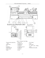
Fig.14-1 Structure of foot brake
1 Emergency stop, spindle start
button
2 Power switch
3 Pin
4 Left support
5 Tension spring arm
6 Tension spring
7 Pedal
8 Pressure rod
9 Connection rod
10 Starting lever
11 Steel band
12 Tightening screw rod
13 Upper seat
14 Strain arm
15 Cam
16 Limit switch
17 Dog
18 Limit switch
19 Coolant pump start/stop
button
20 Spindle start/ stop button
Open in K direction.
Note: Operator’
s panel of CS6140 series lathe is located on
change gear cover. That of CS6266B is located on headstock.
Содержание CS6140 Series
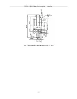
Страница 16: ...CS6140 CS6140B Series Turning machine Instructions 4 3 Fig 4 2 Bearing location diagram ...
Страница 31: ...CS6140 CS6140B Series Turning machine Instructions 6 2 Fig 6 1a Location of electrical parts ...
Страница 32: ...CS6140 CS6140B Series Turning machine Instructions 6 3 Fig 6 1b Location of electrical parts of CS6266B ...
Страница 33: ...CS6140 CS6140B Series Turning machine Instructions 6 4 Fig 6 2a Electric schematic diagram 1 ...
Страница 34: ...CS6140 CS6140B Series Turning machine Instructions 6 5 Fig 6 2a Electric schematic diagram 2 ...
Страница 35: ...CS6140 CS6140B Series Turning machine Instructions 6 6 Fig 6 2b Electric schematic diagram of CS6266B 1 ...
Страница 36: ...CS6140 CS6140B Series Turning machine Instructions 6 7 Fig 6 2b Electric schematic diagram of CS6266B 2 ...
Страница 48: ...CS6140 CS6140B Series Turning machine Instructions 10 2 ...
Страница 60: ...CS6140 CS6140B Series Turning machine Instructions 11 12 Fig 11 12b Structure of spindle nose ISO702 Ⅱ No 8 ...

