CS6140, CS6140B Series Turning machine Instructions
5-2
c) Pitch and feed control knob (9) is used to change pitch and feed in an order from 1 to 15 as indicated on
the data plate. For CS6266B lathe, pitch and feed control knob (6) is used to change pitch and feed in an order
from 1 to 15 as indicated on the data plate.
d) Pitch and feed knob (11) is used to multiply the pitch and feed by means of lead screw and feed rod. For
CS6266B lathe, pitch and feed (7) is used to multiply the pitch and feed by means of lead screw and feed rod.
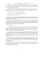
Ⅰ、Ⅱ、Ⅲ、Ⅳ:
Lead screw is engaged to cut a thread.
A
、
B
、
C
、
D
:
Feed rod is engaged to give a feed motion.
Ratio
:Ⅰ
:
Ⅱ
:
Ⅲ
:
Ⅳ
=A:B: C: D=1:2:4:8
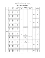
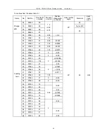
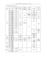
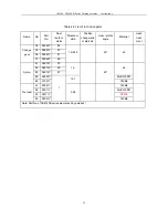
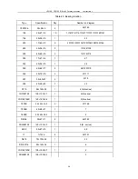
By setting the above levers and knobs accordingly different feeds listed in Table 5-2 are obtained. To ensure
good operating of machine setting levers and knobs should be based upon the principle that a higher spindle
speed matches a finer feed, and vice versa.
The leadscrew can be driven directly by shaft
Ⅰ
through change gears in stead of externally engaged gears in
feeding case in order to cut threads excluded in
Table 5-2.
To do so, thread selector (7) must be set to NEUTRAL
position and pitch and feed knob (11) to
Ⅳ
position. For CS6266B lathe, to do so, thread selector (5) must be set
to NEUTRAL position and pitch and feed knob (7) to
Ⅳ
position.
5.2.2.2 Carriage operation
a) Feed axis selector and rapid traverse button (21) is used to move the carriage or rapidly traverse it in
the direction it is set. For CS6266B lathe, feed axis selector and rapid traverse button (13) is used to move the
carriage or rapidly traverse it in the direction it is set. To rapidly traverse the button on head of the lever should be
pressed and held till the carriage moves to the desired position.
b) Half nut lever (18) is used to move the carriage back and forth along the bed when cutting threads. The
half nut is closed when lever (18) is turned clockwise and separated when lever (18) is turned counter-clockwise.
For CS6266B lathe, half nut lever (8) is used to move the carriage back and forth along the bed when cutting
threads. The half nut is closed when lever (8) is turned clockwise and separated when lever (8) is turned
counter-clockwise.
c) Apron hand-wheel (13), cross slide handle (14) and compound rest handle (20) are all manual controls.
Each of them has a dial on its base to indicate distance moved. For CS6266B lathe, apron hand-wheel (11), cross
slide handle (9) and compound rest handle (19) are all manual controls. Each of them has a dial on its base to
indicate distance moved.
5.2.2.3 For other controls, see the operation diagram. When spindle control lever (12) is put to the upper position,
the spindle starts to run forward; when it is put to the lower position the spindle starts to run backward; when it is
put to the middle position the spindle stops.
Содержание CS6140 Series
Страница 16: ...CS6140 CS6140B Series Turning machine Instructions 4 3 Fig 4 2 Bearing location diagram ...
Страница 31: ...CS6140 CS6140B Series Turning machine Instructions 6 2 Fig 6 1a Location of electrical parts ...
Страница 32: ...CS6140 CS6140B Series Turning machine Instructions 6 3 Fig 6 1b Location of electrical parts of CS6266B ...
Страница 33: ...CS6140 CS6140B Series Turning machine Instructions 6 4 Fig 6 2a Electric schematic diagram 1 ...
Страница 34: ...CS6140 CS6140B Series Turning machine Instructions 6 5 Fig 6 2a Electric schematic diagram 2 ...
Страница 35: ...CS6140 CS6140B Series Turning machine Instructions 6 6 Fig 6 2b Electric schematic diagram of CS6266B 1 ...
Страница 36: ...CS6140 CS6140B Series Turning machine Instructions 6 7 Fig 6 2b Electric schematic diagram of CS6266B 2 ...
Страница 48: ...CS6140 CS6140B Series Turning machine Instructions 10 2 ...
Страница 60: ...CS6140 CS6140B Series Turning machine Instructions 11 12 Fig 11 12b Structure of spindle nose ISO702 Ⅱ No 8 ...


