CS6140, CS6140B Series Turning machine
Instructions
11-4
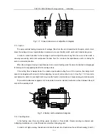
Adjusting nut
Chain
Tension wheel
Fig. 11-5 Chain tension adjustment diagram
11.3 Tailstock
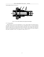
A stop dog (6) fixed in the taper hole of the tailstock is to prevent the tool held from rotating. The tailstock can
move crosswise on the single-direction ways. Cross adjustment is performed with screw (1). Before adjusting be
sure to unclamp the tailstock and loosen the screw (2). After completion of adjustment tighten screw (2) again.
When resetting the tailstock, make sure that flanges (8) are in alignment. See Fig. 11-6.
The tailstock can move on the bed ways and be clamped and locked in position with the eccentric shaft. The
clamping force is adjusted with nut (3) and (4). When tailstock is heavily loaded nut (5) is used to clamp it as well as
the eccentric shaft.
When the clamping lever is released the tailstock is supported on four rolling bearings with spring seats, clear
of bed ways. That makes it an ease for the tailstock to move along the bed ways. The clearance between tailstock
and bed ways is adjusted with screw (7). Before adjusting the tailstock should be locked to ensure proper contact
between tailstock and bed ways and prevent bearings from being broken.
Содержание CS6140 Series
Страница 16: ...CS6140 CS6140B Series Turning machine Instructions 4 3 Fig 4 2 Bearing location diagram ...
Страница 31: ...CS6140 CS6140B Series Turning machine Instructions 6 2 Fig 6 1a Location of electrical parts ...
Страница 32: ...CS6140 CS6140B Series Turning machine Instructions 6 3 Fig 6 1b Location of electrical parts of CS6266B ...
Страница 33: ...CS6140 CS6140B Series Turning machine Instructions 6 4 Fig 6 2a Electric schematic diagram 1 ...
Страница 34: ...CS6140 CS6140B Series Turning machine Instructions 6 5 Fig 6 2a Electric schematic diagram 2 ...
Страница 35: ...CS6140 CS6140B Series Turning machine Instructions 6 6 Fig 6 2b Electric schematic diagram of CS6266B 1 ...
Страница 36: ...CS6140 CS6140B Series Turning machine Instructions 6 7 Fig 6 2b Electric schematic diagram of CS6266B 2 ...
Страница 48: ...CS6140 CS6140B Series Turning machine Instructions 10 2 ...
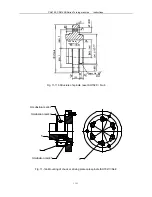
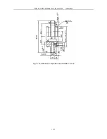
Страница 60: ...CS6140 CS6140B Series Turning machine Instructions 11 12 Fig 11 12b Structure of spindle nose ISO702 Ⅱ No 8 ...


