CS6140, CS6140B Series Turning machine Instructions
6-1
6 Electrical part of the machine
6.1 Preparation before applying power source
After installation, following checks must be taken to guarantee safe operation.
1) Observation check. Open the door of cabinet and make sure that no element inside is damaged. Make sure
that every connector and wires are connected firmly.
2) Be sure that no water has come into the cabinet and it is dry inside.
3) Measure the power supply with a multimeter and be sure it is the required specifications.
6.2
Operation and wire connection
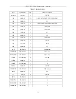
Fig.6-1 is parts location diagram. Fig.6-2 is electric schematic diagram. Fig.6-3 is wire connection diagram.
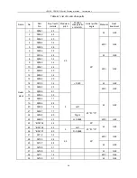
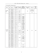
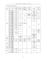
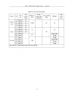
Table 6-1 lists all electrical parts.
The machine operates on power source of 3-phase AC 220V, 380V, 400V, 415V, 420V, 440V, 500V, 575V, 600V,
660V, and 50Hz/60Hz, There is no general fuse on the machine, so user should connect a desired fuse to the
power source circuit. CS6266B lathe has power light and coolant light.
Connect the power line to the terminal board, which is installed in the front support of the machine and accessed
through the window at rear side of the support. Connect and fasten the ground wire to the earth screw.
Supply electric power for machine by closing the power switch QS1. Lamp EL is lit up.
The motor starts to run when SB3 or SB4 is pushed and stops when SB2 or SB5 is pushed.
Coolant pump M2 is unable to be started unless the motor is running. Coolant pump is started using SB6 and
stops as the motor stops.
Work lamp EL is turned on and off with switch SA1 on condition that power switch QS1 is closed.
Limit switch SQ1 breaks the related contacts and cuts power from motor and from electric control unit to ensure
safety of service man when the change gears cover is opened for maintenance and adjustment.
The electric parts can not be accessed unless the second protection door, which is installed to avoid accidental
touch of electric parts, is removed. SQ5 is a door trip and is used to disconnect control circuit.
The right to change the data of this part for meeting customers’
requirement is reserved.
Содержание CS6140 Series
Страница 16: ...CS6140 CS6140B Series Turning machine Instructions 4 3 Fig 4 2 Bearing location diagram ...
Страница 31: ...CS6140 CS6140B Series Turning machine Instructions 6 2 Fig 6 1a Location of electrical parts ...
Страница 32: ...CS6140 CS6140B Series Turning machine Instructions 6 3 Fig 6 1b Location of electrical parts of CS6266B ...
Страница 33: ...CS6140 CS6140B Series Turning machine Instructions 6 4 Fig 6 2a Electric schematic diagram 1 ...
Страница 34: ...CS6140 CS6140B Series Turning machine Instructions 6 5 Fig 6 2a Electric schematic diagram 2 ...
Страница 35: ...CS6140 CS6140B Series Turning machine Instructions 6 6 Fig 6 2b Electric schematic diagram of CS6266B 1 ...
Страница 36: ...CS6140 CS6140B Series Turning machine Instructions 6 7 Fig 6 2b Electric schematic diagram of CS6266B 2 ...
Страница 48: ...CS6140 CS6140B Series Turning machine Instructions 10 2 ...
Страница 60: ...CS6140 CS6140B Series Turning machine Instructions 11 12 Fig 11 12b Structure of spindle nose ISO702 Ⅱ No 8 ...


