
CS6140, CS6140B Series Turning machine
Instructions
14-1
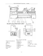
14 Foot brake
14.1 Application and function
This brake is designed for stopping the high running main motor and other transmission units of machine. It is
simply constructed, efficient, independent and easy to service.
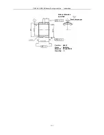
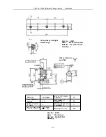
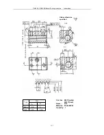
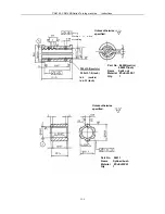
14.2 Structure and working principle
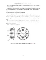
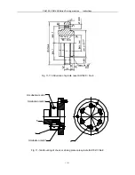
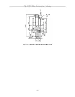
Fig.14-1 shows the structure of the foot brake. It consists of pedal, connection rod, support, seat, cam, strain
arm, pulley, steel band, braking assembly and electrical unit. As soon as the pedal (6) is trodden, cam (15) will
disconnected the over-travel limit switch (16) with the help of strain arm (14), cut off the power to main motor. The
motor is thus stopped under the combined action of strain arm (14) and steel band (11).
The spindle is unable to re-start unless the starting lever (10) is set to NEUTRAL position.
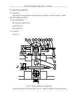
14.3 Electric unit
Fig. 6-2a is electric schematic diagram of CS6140 series equipped with foot brake and Fig. 6-3a is electric
connection diagram. Fig. 6-2b is electric schematic diagram of CS6266B and Fig. 6-3b is electric connection
diagram of CS6266B.
14.3.1 For electrical unit of foot brake, please refer to section
6
electrical part of the machine.
The main motor of machine can’
t be started unless the starting lever is set to NEUTRAL position. See
Fig.14-1.
When the starting lever (10) is set to NEUTRAL position, dog (17) operates and close SQ3 of limit switch (18).
In this case the contactor is closed when SB3 or SB4 (KM1) is depressed, and the main motor is operatable.
When it is necessary to stop the rotating spindle, step on pedal (7) and the limit switch (16) SQ2 is switched
off, meanwhile the main motor is disconnected to a stop. The main motor can also be stopped by depressing SB2 or
SB5 and it can not be restarted unless the starting lever is set to NEUTRAL position.
During turning operation control circuit can be disconnected by depressing SB5 in a case of emergency.
14.3.2 Adjustmen
When starting lever is set to NEUTRAL position, dog (17) should be adjusted so that SQ3 of limit switch (18) is
in a compressed state. Some adjustment should be made so that limit switch (16) SQ2 is in released state when no
pedal is stepped and in compressed state when pedal is stepped.
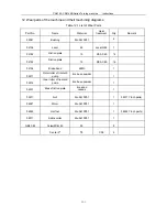
See Table 6-1 for electric components.
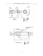
14.4 Set up
The swivel angle of pedal (7) is changed by adjusting the length of steel band (11) using the nut of tightening
screw rod (12). The height of pedal (7) is changed after loosing the pressure rod (8). The pedal must be locked
again after adjustment. Cam (15) is adjusted so that the machine brakes to a steady stop when limit switch (16) is
switched off. Limit switch (18) should be adjusted so that it is closed prior to starting of spindle.
Содержание CS6140 Series
Страница 16: ...CS6140 CS6140B Series Turning machine Instructions 4 3 Fig 4 2 Bearing location diagram ...
Страница 31: ...CS6140 CS6140B Series Turning machine Instructions 6 2 Fig 6 1a Location of electrical parts ...
Страница 32: ...CS6140 CS6140B Series Turning machine Instructions 6 3 Fig 6 1b Location of electrical parts of CS6266B ...
Страница 33: ...CS6140 CS6140B Series Turning machine Instructions 6 4 Fig 6 2a Electric schematic diagram 1 ...
Страница 34: ...CS6140 CS6140B Series Turning machine Instructions 6 5 Fig 6 2a Electric schematic diagram 2 ...
Страница 35: ...CS6140 CS6140B Series Turning machine Instructions 6 6 Fig 6 2b Electric schematic diagram of CS6266B 1 ...
Страница 36: ...CS6140 CS6140B Series Turning machine Instructions 6 7 Fig 6 2b Electric schematic diagram of CS6266B 2 ...
Страница 48: ...CS6140 CS6140B Series Turning machine Instructions 10 2 ...
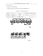
Страница 60: ...CS6140 CS6140B Series Turning machine Instructions 11 12 Fig 11 12b Structure of spindle nose ISO702 Ⅱ No 8 ...


