CS6140, CS6140B Series Turning machine
Instructions
11-7
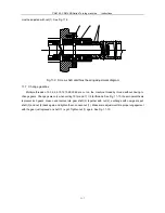
must be adjusted with nut (1). See Fig. 11-9.
2
3
1
Fig.11-9 Screw shaft anti-thrust bearing adjustment diagram
11.7 Change gearbox
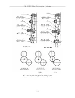
Multiple threads of 2,3,4,5,6,10,12,15,20,30,60 are cut on the machine thread by thread without having to
change gears. Change gears only when cutting 19 tpi and 11 1/2 tpi threads. See Fig. 11-10, those in parenthesis
represent inch gears. Loosen and remove idle gear shaft (3) together with nut (2), exchange with new gears, put
shaft (3) and nut (2) back again and tighten them. Loosen nut (1). Make some adjustment till a proper engagement
with the gear just replaced on shaft
Ⅰ
is got. Tighten nut (1) again. See Fig. 11-10.
Содержание CS6140 Series
Страница 16: ...CS6140 CS6140B Series Turning machine Instructions 4 3 Fig 4 2 Bearing location diagram ...
Страница 31: ...CS6140 CS6140B Series Turning machine Instructions 6 2 Fig 6 1a Location of electrical parts ...
Страница 32: ...CS6140 CS6140B Series Turning machine Instructions 6 3 Fig 6 1b Location of electrical parts of CS6266B ...
Страница 33: ...CS6140 CS6140B Series Turning machine Instructions 6 4 Fig 6 2a Electric schematic diagram 1 ...
Страница 34: ...CS6140 CS6140B Series Turning machine Instructions 6 5 Fig 6 2a Electric schematic diagram 2 ...
Страница 35: ...CS6140 CS6140B Series Turning machine Instructions 6 6 Fig 6 2b Electric schematic diagram of CS6266B 1 ...
Страница 36: ...CS6140 CS6140B Series Turning machine Instructions 6 7 Fig 6 2b Electric schematic diagram of CS6266B 2 ...
Страница 48: ...CS6140 CS6140B Series Turning machine Instructions 10 2 ...
Страница 60: ...CS6140 CS6140B Series Turning machine Instructions 11 12 Fig 11 12b Structure of spindle nose ISO702 Ⅱ No 8 ...


