


Fault Location Mode
51
Chapter 4
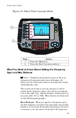
Fault Location Mode
Fault location identifies the position of impedance dis-
continuities (reflections) within the antenna/feeder
system. The measurement results are displayed on an
x-y graph. Distance from the Site Analyzer is shown
on the x-axis, while relative magnitude of the disconti-
nuity is shown on the y-axis.
Before you make a fault location measurement, be
sure that you have the following items and informa-
tion:
•
A Bird Calibration Combination (Cal Combo) cali-
bration unit
•
All necessary cables and adapters of the correct
size and connector type.
•
The velocity of propagation for the cable type you
will measure (obtain from the cable manufacturer)
•
Number of data points to use in making the dis-
tance to fault measurement (user choice)
This chapter describes how to make a fault location
measurement and provides step by step instructions.
In addition, this chapter also describes how to set and
move markers. For information and instructions to
save and recall traces, refer to Save and Recall, page
91.
To make a fault location measurement, follow the pro-
cedures in this chapter in the order they are pre-
sented.
Determine the Power of the Component Being Tested
Use a service monitor, power meter, or spectrum ana-
lyzer to check that the component being tested does
not have power greater than +22 dBm.
Содержание SITE ANALYZER SA-1700EX
Страница 2: ...This page is not blank...
Страница 8: ...Bird Site Analyzer vi...
Страница 9: ...vii...
Страница 30: ...Bird Site Analyzer 16...
Страница 142: ...Bird Site Analyzer 128...
Страница 148: ...Bird Site Analyzer 134...
Страница 159: ...Maintenance 145 Measured Return Loss dB...
Страница 161: ...Maintenance 147 SA 6000 Measurement Uncertainty Return Loss after one refresh Measured Return Loss dB Directivity...
Страница 167: ...Maintenance 153 the number of data points you wish measure 238 475 949...


