KBF-LQC (E5.2) 12/2010
page 64/106
Setting:
To check the response temperature of the safety device class 3.1, turn on the chamber and set the de-
sired set point at the temperature controller.
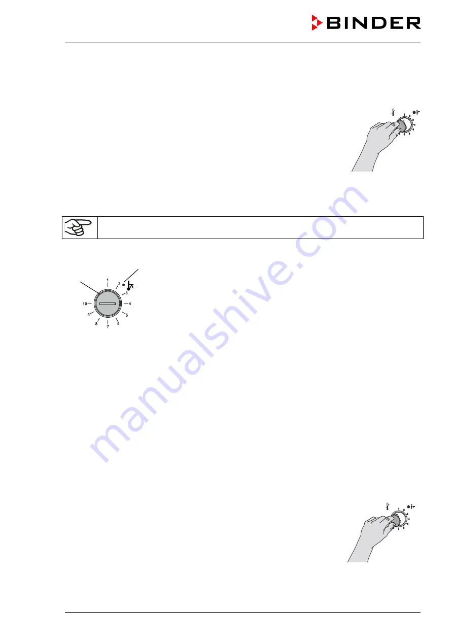
The sections of the scale from 1 to 10 correspond to the temperature range from 0 °C /
32°F
to 120 °C /
248°F
and serve as a setting aid.
•
Turn the control knob (14) of the safety device using a coin to its end-stop (po-
sition 10) (unit protection).
•
When the set point is reached, turn back the control knob (14) until its trip point
(turn it anti-clockwise).
•
The trip point is identifiable by the red alarm lamp (14a), the message “TEMP
ALARM” on the controller display, and the buzzer. Reset the buzzer with
RESET key on the controller.
•
The optimum setting for the safety device is obtained by turning the control
knob clockwise by approximately two scale divisions, which leads to extinguish
the red alarm lamp (14a).
Figure 21: Setting
safety device class
3.1
Check the setting regularly and adjust it following changes of set-point or charge.
11.3.2 Temperature safety device class 3.2
The safety device class 3.2 is equivalently set to a minimum temperature the
unit will not fall below. This protection against forbidden low temperatures
can for example serve to protect sensitive cultures from cooling down too
much.
If the control knob (15) is turned to its minimum (position 1), the safety de-
vice class 3.2 is without effect. If it is set to a temperature somewhat lower
than that selected by means of the controller, it functions as a protective
device for the material under treatment.
If the temperature safety device class 3.2 has assumed regulation, identifiable by the red alarm lamp
(15a) lighting up, the message “TEMP ALARM” on the controller display, and the buzzer, please proceed
as follows:
•
Reset the buzzer with RESET key on the controller.
•
Disconnect the unit from the power supply.
•
Have examined and rectified the cause of the fault by an expert.
•
Start up the unit again as described in chap. 5.
Setting:
To check the response temperature of the safety device class 3.2, put the unit into operation and set the
desired set point at the temperature controller.
The sections of the scale from 1 to 10 correspond to the temperature range from -40 °C /
-40°F
to +160
°C /
320°F
and serves as a setting aid.
•
Turn the control knob (15) of the safety device by means of a coin to position
1 (thermostat without effect).
•
When the set point is reached, reset the safety device to its trip point (turn it
clockwise).
•
The trip point is identifiable by the red alarm lamp (15a), the message “TEMP
ALARM” on the controller display, and the buzzer. Reset the buzzer with
RESET key on the controller.
•
The optimum setting for the safety device is obtained by turning the control
knob anti-clockwise by approximately two scale divisions, which leads to ex-
tinguish the red alarm lamp (15a).
Figure 22: Setting
safety device class 3.2
(15a)
(15)
Содержание APT.line KBF-LQC Series
Страница 102: ...KBF LQC E5 2 12 2010 page 102 106 21 7 Dimensions KBF LQC 240...
Страница 103: ...KBF LQC E5 2 12 2010 page 103 106 21 8 Dimensions KBF LQC 720...
Страница 107: ......


