35
User Manual
Model PCS
Pneumatic Motion Control System
APPENDIX 6
PFCN PROBE ADJUSTMENT AND REPLACEMENT INSTRUCTIONS
Probe Adjustment
Probe output calibration is normally not required. Every PFCN is calibrated at the factory for 0 to 10 V
DC output fully retracted to fully extended. If readjustment is necessary in your application, follow the
instructions below:
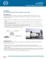
1. Install the PFCN in your application. Remove the rear end cap exposing the probe and four adjustment
screws.
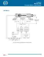
2. Apply 24 VDC power to the probe and monitor the feedback voltage. Connector pin identification is
shown in the illustration below.
3. Position the actuator to full retract at 80 psi. Adjust the output as close to zero as possible using the
coarse adjustment “RET(CS),” and then the fine adjustment “RET(FN).”
4. Position the actuator to full extend at 80 psi. Adjust the output to 10 V DC using the coarse adjustment
“EXT(CS),” and then the fine adjustment “EXT(FN).”
5
3
A
B
M
I
B
-
4
4
-
0
0
8
:
e
c
n
a
t
s
i
s
s
A
l
a
c
i
n
h
c
e
T
m
o
c
.
a
b
m
i
b
.
w
w
w
GROUND
FEEDBACK OUTPUT
24 VDC INPUT
5
3
A
B
M
I
B
-
4
4
-
0
0
8
:
e
c
n
a
t
s
i
s
s
A
l
a
c
i
n
h
c
e
T
m
o
c
.
a
b
m
i
b
.
w
w
w
GROUND
FEEDBACK OUTPUT
24 VDC INPUT
Probe Replacement
The PFCN probe is not a wear part and normally will not need replacement. If replacement is necessary,
follow the instructions below:
1. Using an allen wrench, remove the four socket head cap screws on the rear of the cylinder.
2. Remove the rear cap. Carefully detach the plastic connector that secures the M8 DIN connector to the
probe terminals.
3. Remove the two long screws that secure the probe in the cylinder. Then pull the probe out of the cylinder.
4. Gently insert the replacement probe into the cylinder, rotating it until its through holes align with the screw
holes in the cylinder. Tighten the screws, then reattach the end cap.


