31
User Manual
Model PCS
Pneumatic Motion Control System
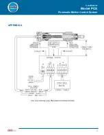
Always insert a
jumper between
TB1 ground and
TB2 terminal C,
as shown by the
dotted blue line
to the right.
PFCN ELECTRICAL AND PNEUMATIC CONNECTIONS
Note that for the PFCN, power to the probe MUST come from 24 VDC supplied to the PCS control, and NOT
the 10 VDC that the PCS produces from terminal A of TB2.
If the Q (quick connect) option was selected, the connection to terminal A of TB2 must be removed and the lead
reinserted into the +24VDC terminal of TB1.
Also, insert a jumper between TB1 ground and TB2 terminal C (dotted blue line).
Always insert a
jumper between TB1
ground and TB2
terminal C, as shown
by the dotted blue
line to the right.


