


- 40 -
INST
ALLA
TION
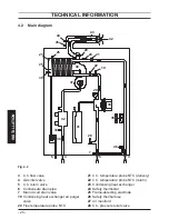
INSTALLATION
6.4 Overall dimensions
The boiler respects the following dimen-
sions:
Fig. 6.2
Ø80
Ø80
Ø100
Ø80
400
200
120
266
222
70
0
62
3
25
115
115
25
20
200
117
129
60
120
290
149
97
50
A
A
B
B
C
C
C
D
E
F
G
G
H
H
I
I
A
Flue outlet / air intake pipe (co-axial ø
100/60)
B
Flue outlet pipe ø 80 mm (twin kit)
C
Air intake pipe ø 80 mm (twin kit)
D
Bracket
E
Electric connections area
F
Condensate drain connection area
G
C.h. flow
H
Gas
I
C.h. return
6.5 Joints
The boiler uses the following fittings:
Functions
Pipe sizes
(o.d)
Gas, c.h. return, c.h. flow
ø 22
Pressure relief valve
ø 15
Condensate drain
ø 25 (plastic)
sizes in mm o.d.
Condensate drain to be realised with min.
pipe ø 30 mm
6.6 Mounting the boiler
• Assemble the pre-piping kit bracket by
screwing the four screws "J" Fig. 6.3.
• Fix the c.h. valves "L" and the gas cock
"M" with the remaining forks "K" to the
prepiping kit bracket.
• Mount the bracket of the prepiping kit to
the wall (See also section "Installing the
bracket" pag. 39).
• Fix the Ø 22 mm copper pipes “N” to the
valves “L – M” using the ¾” gaskets.
• Take the protective caps off the boiler
pipework.
• Thoroughly clean the connections.
• Mount the boiler on its bracket.
• Fix the c.h. valves "L" and gas cock "M"
(¾") to the boiler using the ¾" gaskets.
Содержание Activ A 25S
Страница 79: ... 79 MAINTENANCE MAINTENANCE Fig 9 25 Winter ...
Страница 82: ... 82 NOTES ...
Страница 83: ......