3
101
E
N
G
IN
E ASS
E
M
B
LY AN
D CO
NTRO
LS
1
2
3
4
32
6Nm
10Nm
6Nm
Element
Cables
Resistance values
Pick up
Red – Green
100
Ω
± 20%
Stator
Black - Black
0,46
Ω
±20%
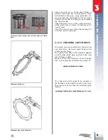
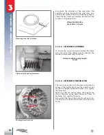
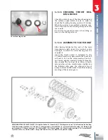
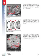
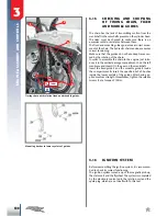
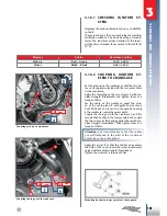
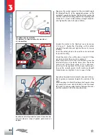
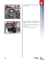
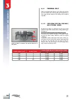
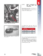
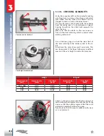
Coupling pick up to crankcase.
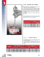
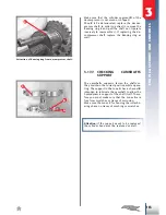
Coupling chain guard to crankcase.
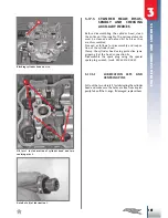
Mounting bushes in lower eyelets of chain guard.
3.16.1 CHECKING IGNITION SY-
STEM
Degrease the various elements and carry on with the
controls.
The main control is the one concerning the electrical
verification which can be done by using a standard
tester. The resistance values detected at the termi
-
nal heads must respect those carried in the table (at
20°C).
3.16.2 COUPLING IGNITION SY-
STEM TO CRANKCASE
Set the pick-up on the crankcase so that the two ho
-
les on its support coincide with the two outer holes
on the crankcase.
Apply the threading of the two screws
1
with me
-
dium strength threadlocker and tighten them at a
torque of 6Nm.
Lay the cable on the crankcase, apply the groo
-
ve of the cable gland
2
with gasket paste
(code
3625000000)
and insert it in the specific housing
n the crankcase, removing excess paste.
Couple the chain guard to the crankcase, insert the
two 6.2x9x9 bushes in the lower eyelets and couple
the two screws
1
after having applied them with me
-
dium strength threadlocker. Then tighten them at a
torque of 10Nm.
Attention:
pay close attention so that the cables
are well fastened to the wall of the crankcase
halves near the cable gland.
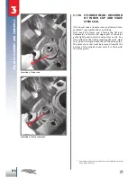
Apply the oil jet
3
so that the bottom edge enters
the hole of the cover. Insert the screw
4
previously
spread with medium strength threadlocker.
Tighten the screws at a torque of 6Nm.

