

3
83
E
N
G
IN
E ASS
E
M
B
LY AN
D CO
NTRO
LS
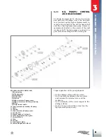
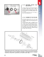
1
4
5
7
8
6
2
3
4Nm
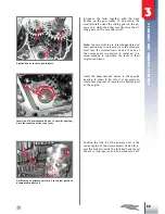
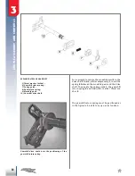
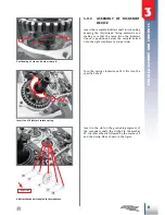
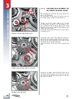
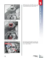
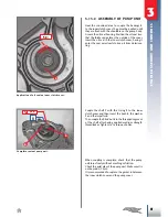
3.11.1 ASSEMBLY OF LOW PRES-
SURE PUMP
Insert the internal rotor
1
on the shaft
2
so that
the dot on the face of the rotor faces inwards.
Then insert the roller
3
on the shaft.
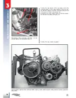
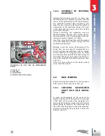
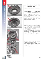
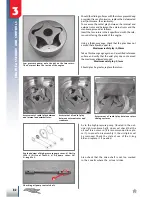
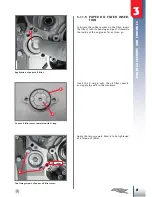
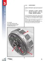
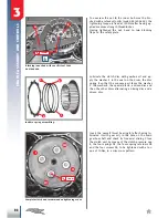
Use motor oil to lubricate the seat of the rotors
on the outside of the crankcase half, insert the
external rotor
4
and the internal shaft-rotor unit
in its proper seat.
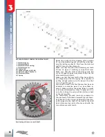
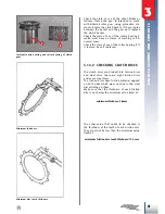
Insert the ball
5
(diameter 5.5mm) and the re
-
spective compression spring
6
.
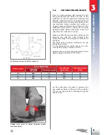
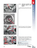
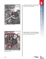
Lubricate with motor oil and, while rotating the
protruding segment of the drive shaft (from the
outside of the right crankcase half), make sure
it rotates freely and does not jam.
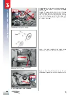
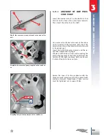
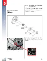
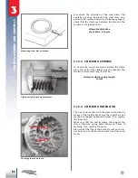
Fasten the cover
7
to the crankcase with the
three screws
8
, which must first be spread with
medium strength threadlocker. These screws
must be tightened at a torque of 4Nm.
Shaft, low pressure pump, internal rotor and roller
unit.
Complete low pressure pump coupled to the crankca-
se.
Coupling low pressure pump cover to crankcase.