3
126
E
N
G
IN
E ASS
E
M
B
LY AN
D CO
NTRO
LS
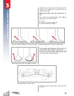
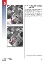
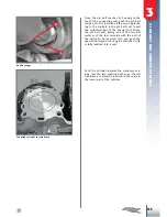
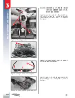
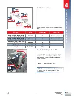
Application of guide bushes 4 and gasket 5 to
cylinder.
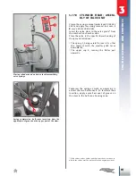
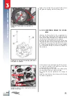
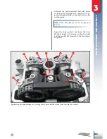
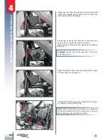
Tightening order of screws coupling the head and
cylinder to crankcase.
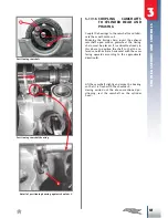
Application of components for coupling cylinder head
and cylinder to crankcase.
Apply to the cylinder the two guide bushes
4
and
the gasket
5
coupling with the cylinder head.
5
4
3.17.15 COUPLING HEAD TO CYLIN-
DER
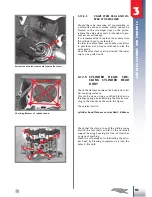
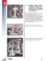
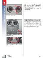
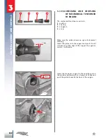
Introduce the timing chain in the compartment on
the cylinder head. Keeping the chain tight, place the
head on the gasket making sure it inserts perfectly
into the two centring bushes on the cylinder.
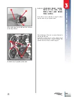
Lubricate the four washers
8
and insert them into
their specific seats on the outside and inside of the
cylinder head. Then insert the four M10x1.25 screws
9
- after having lubricated them- and the M6x80
screw
14
which connect the head and cylinder to
the crankcase.
In two moments, proceed tightening the four screws
in a criss-cross pattern. Start with one of the two
screws inside the cylinder head.
The first tightening can be done at 30÷40Nm, while
the second and last one is fixed at 55Nm.
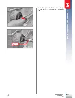
The screw
14
must be tightened at a torque of
10Nm.
Keep the chain lifted so that it does not fall inside
the chain compartment.
II
III
I
Iv
30÷40Nm 55Nm
10Nm

