


3
96
E
N
G
IN
E ASS
E
M
B
LY AN
D CO
NTRO
LS
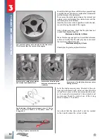
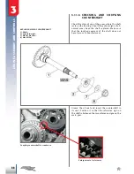
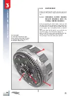
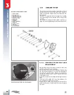
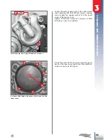
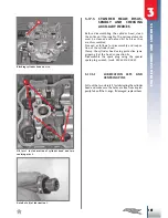
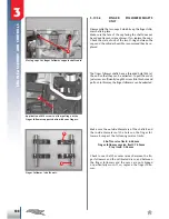
EXPLODED VIEW OF WATER PUMP
1) Drive shaft
2) O-ring 5.5x1;
3) Bearing 10x19x5;
4) Oil seal 12x30x7;
5) Bush 8x12x10;
6) Impeller;
7) Washer;
8) Blind nut M6x1;
9) Gasket;
10) Gasket cover;
11) Washer;
12) Screw M6x40.
3.13
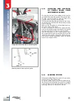
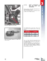
CooLANt PUMP
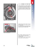
The water pump must guarantee, depending on the set
rotation speed, the correct flow rate of the coolant in
order to extract the needed amount of heat from the
thermal unit.
The shaft
1
is supported by two bearings
3
and sealing
of coolant and gear oil is ensured by the O-ring
2
and
oil seal
4
.
The impeller 6 is fastened to the shaft
1
and the cou
-
pling is ensured by tightening the nut
8
onto the shaft
1
.
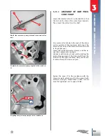
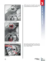
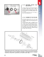
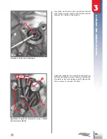
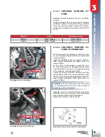
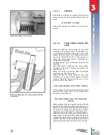
3.13.1 CHECKING PUMP UNIT AND
DISASSEMBLY
Disassembly of the entire pump unit can be done only
with the entire clutch cover removed.
Disassembly of the pump unit is performed by removing
the nut
8
which allows you to extract the impeller
6
,
the washer
7
, and the shaft
1
. This can be removed by
pressing the threaded part of shaft
1
towards the inside
of the clutch cover.
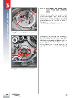
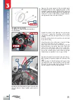
Extract the oil seal
4
and, heating the bearings
3
, remove
them.
Once the shaft is pulled off 1 from the crankcase, it is
recommended to replace the O-ring
2
.
Replace the oil seal
4
every time and if the bush
5
is
marked in the area of contact with the oil seal, replace
it as well.
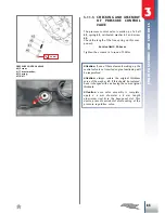
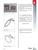
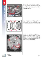
Complete internal clutch cove of water pump.