3
82
E
N
G
IN
E ASS
E
M
B
LY AN
D CO
NTRO
LS
A
Should the sliding surfaces with the rotors present deep
or evident traces of corrosion, replace the deteriorated
part (in this case, the crankcase).
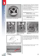
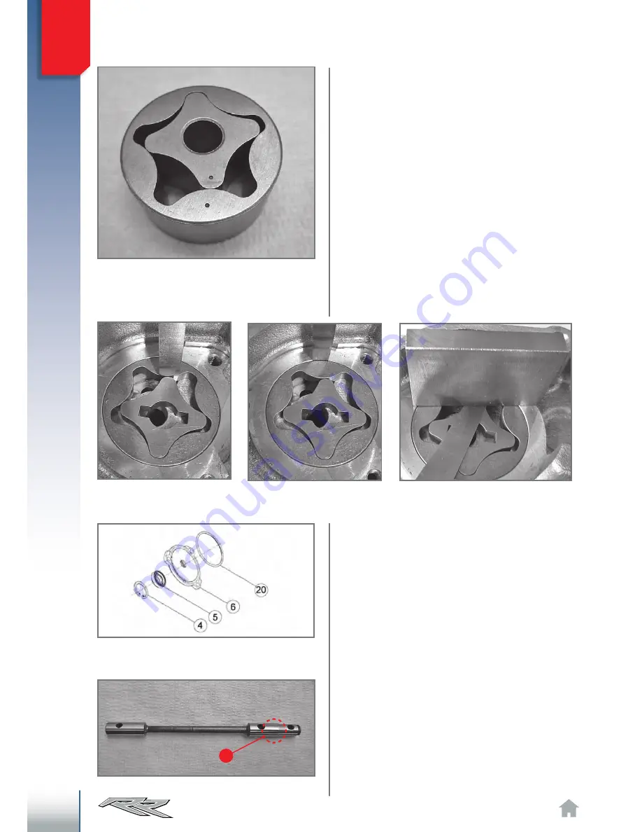
To measure the radial play between the internal and
external rotor and between the external rotor and the
crankcase, proceed as follows:
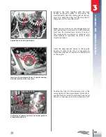
Insert the two rotors in their specific seat with the refe
-
rence dot facing the inside of the engine.
Using a thickness gauge, check that the play does not
exceed that allowed, equal to:
Maximum radial play: 0,20mm
Take a thickness gauge again and a rectified reference
surface and verify that the axial play does not exceed
the maximum allowed amount:
Maximum axial play: 0,1mm
Should play be greater, replace the rotors.
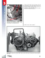
As to the high-pressure pump (located in the out
-
side right crankcase half), one must check that the
oil seal
5
is not worn (it is recommended to repla
-
ce it). In order to disassembly it, the circlip
4
must
be removed. Check the state of use of the O-ring
20
and replace it if needed.
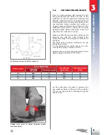
Also check that the drive shaft is not too marked
in the zone
A
where the oil seal slides.
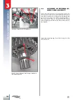
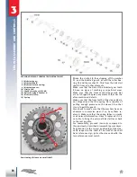
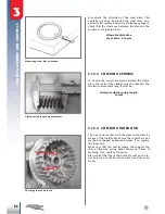
Low pressure pump: note the dot on the two rotors.
The dot must face the inside of the engine.
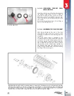
Exploded view of high-pressure pump cover. 4) Circlip
JS24; 5) Oil seal 10x22.6; 6) Oil pump cover; 20)
O-ring 45x2.
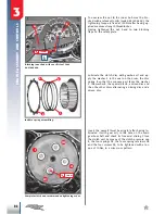
Checking oil pump control shaft.
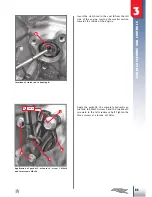
Assessment of radial play between
and internal and external rotor.
Assessment of radial play
between external rotor and
crankcase.
Assessment of radial play between rotors
sliding surfaces.

